Main system status view
This view is displayed by default after starting-up flight execution. It gives an overview of the main subsystems. It is also the entry point to select views to display detailed data of the sub-systems such as Sensor, GNSS/IMU, GNSS or Memory.
To display this view from flight menu proceed as follows.
Select 
Select 
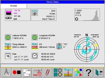
This view gives an overview of the sensor system and the main sub-systems.
Memory and GNSS control are displayed on the upper left and centre. In the area below this controls the status of the system memory as well as the date and time of the system is displayed.
On the right side, the Sensor specific controls are displayed
Select 
See section https://hexagon.atlassian.net/wiki/spaces/FPDOC/pages/44726093583/User+Interface#Navigation-within-the-menu-tree.
Selection of sub-system status views
Select 
GNSS status view
To display this view from flight menu proceed as follows.
Select
Select
Select
Select 
The GNSS control can be touched to display GNSS status view.
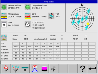
The GNSS status view shows current values for position, altitude, speed over ground, track over ground, date and time. The lower section lists for every satellite in view the satellite number, its status, azimuth and elevation angles and the signal to noise ratios for both of the frequency bands.
At the upper right a sky plot is displayed which graphically displays the positions of the satellites in view as well as the sun.
If display local coordinates is activated and if transformation parameters are available to transform from WGS84 to local coordinates, local coordinates are displayed on this view in addition to WGS84 coordinates. The name of the transformation is also displayed on this view.
Select 
Select 
GNSS-IMU status view
To display this view from flight menu proceed as follows.
Select
Select
Select
Select 
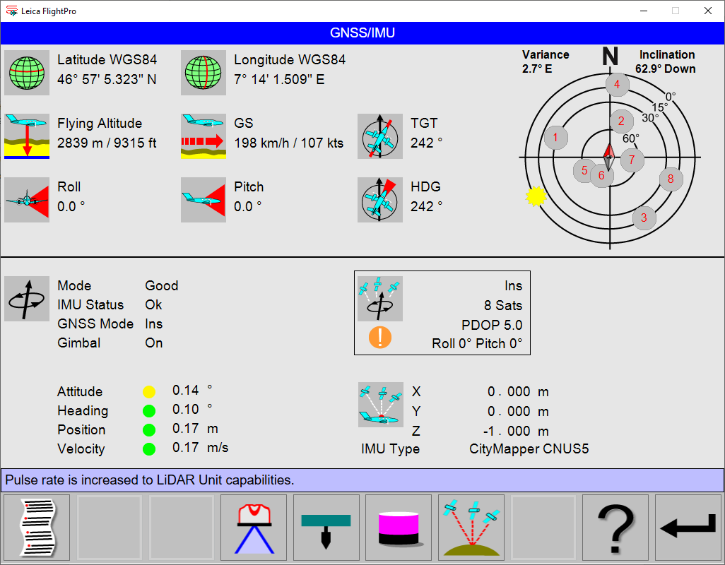
The GNSS-IMU status view displays all position and attitude information provided by the NovAtel SPAN system.
On the lower left side the operational status of the NovAtel SPAN is displayed. All ‘lights’ should be green during the flight mission.
The table shows the colour-coded limits for every parameter and when the colour-code changes. The GNSS control shows an overview of the five parameters are displayed to help the operator with QC task for the GNSS/IMU system. See https://hexagon.atlassian.net/wiki/spaces/FPDOC/pages/44730778581/System+controls#GNSS%2FIMU-control.
|
Parameter |
|
|
|
Typical behaviour |
|---|---|---|---|---|
|
Attitude |
< 0.05° |
0.05° > Attitude < 1° |
>1° |
Show |
|
Heading |
< 0.5° |
0.5° > Heading < 5° |
>5° |
Show |
|
Position |
< 5 m |
5 m > Position < 10 m |
>10 m |
Show |
|
Velocity |
< 0.5 m/s |
0.5 m/s < Velocity > 1.0 m/s |
>1.0 m/s |
Green 0.5 m/s |
As the attitude information is coupled to the GNSS information GNSS data are also displayed in the GNSSIMU view.
A sky plot on the upper right graphically displays the positions of the satellites in view.
Gimbal status:
-
OFF = no data available from mount
-
Available = data received from mount, but not used, because GNSS/IMU real time solution not yet available. (Status on ground)
-
ON = data received from mount. Aircraft frame available, computed based on real-time solution and gimbal data. (Status in-flight)
If display local coordinates is activated and if transformation parameters are available to transform from WGS84 to local coordinates, local coordinates are displayed on this view in addition to WGS84 coordinates. The name of the transformation is also displayed on this view.
Select
Select 
Mass Memory status view
To display this view from flight menu proceed as follows.
Select
Select
Select
Select 
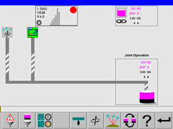
The Mass Memory status view displays information about dataflow from the GNSS/IMU system images. The Sensor control, as well as the Mass Memory control, are displayed on the upper part of the view.
Select
Select 
Mount status view
To display this view from flight menu proceed as follows.
Select
Select
Select
Select
Select 
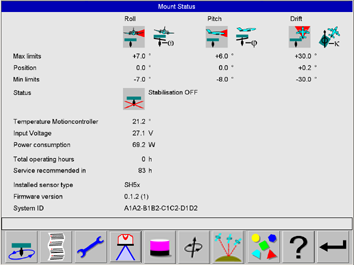
The Mount status view displays information about the gyro-stabilized sensor mount. Details can be found in the corresponding device documentation.
Select 
Select 
Thumbnail and Histogram class view
This view display thumbnails. To each thumbnail a sensor control is displayed. The sensor control shows the metadata to the thumbnail like exposure data and histogram classes.
Various zoom levels can be selected. This allows to display at the same time either:
-
two thumbnails with corresponding sensor controls
-
six thumbnails with corresponding sensor controls
-
12 thumbnails
-
all Camera Head thumbnails of one release
Penta pod: nadir, forward, backward, left, right
Trio pod: nadir forward, backward or nadir, left, right
The latest thumbnail is framed in white colour.
If data for two cameras are displayed on the view, the view is split vertically. Data for camera 1 are displayed on the left side and data for camera 2 are displayed on the right side.
To display this view from flight menu proceed as follows:
Select
Select
Select
Select 
The view shows six thumbnails with corresponding sensor controls.
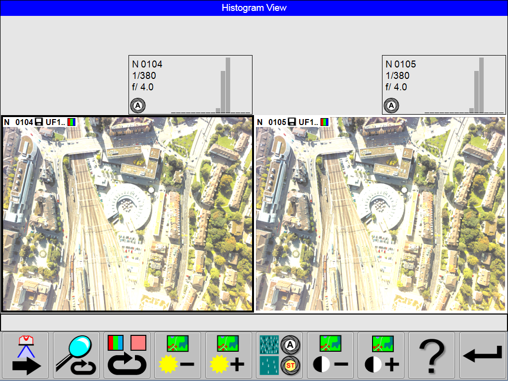
The view shows two thumbnails with corresponding sensor controls.
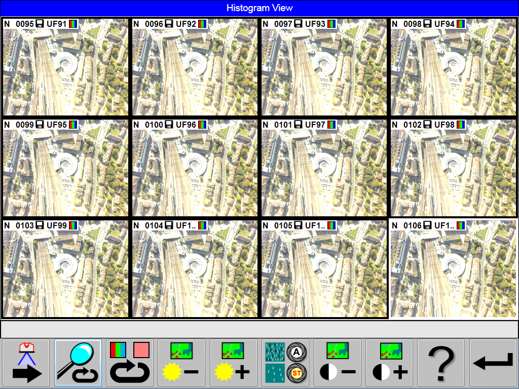
The view shows twelve thumbnails.
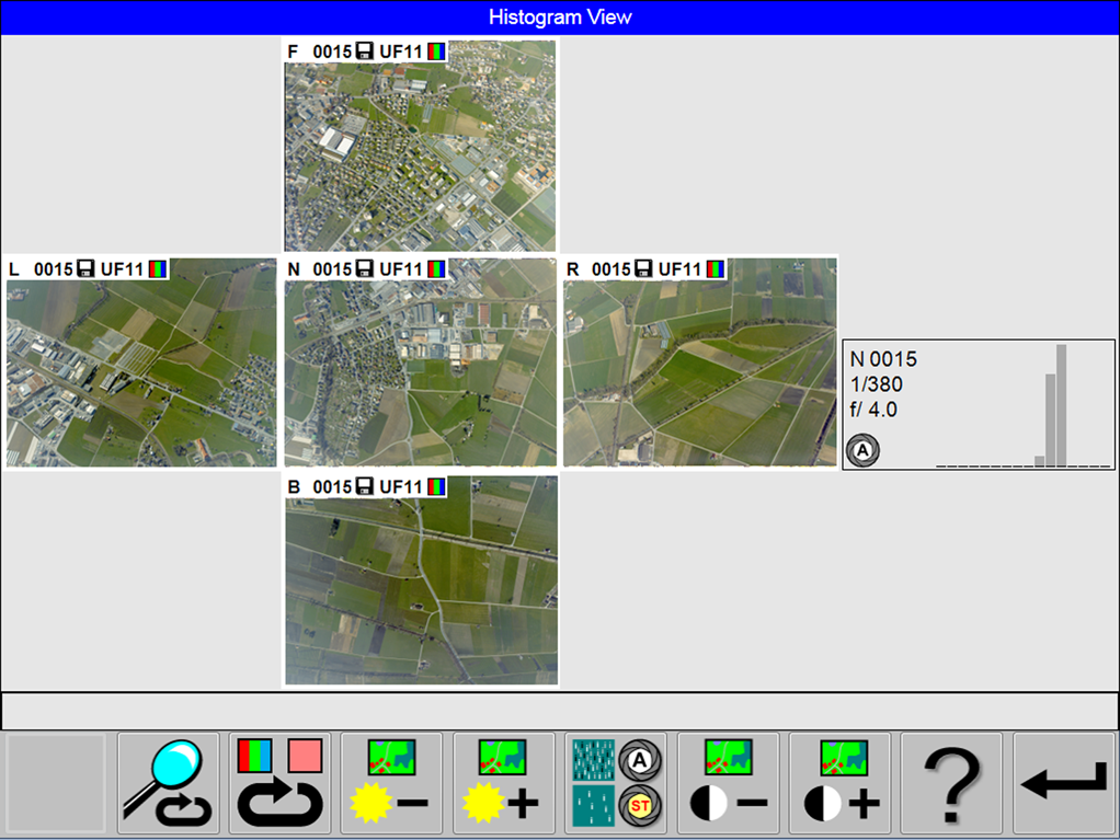
The view shows thumbnails from all Camera Heads with corresponding sensor control for the nadir camera head.
Select 
Select 
Select 
Select 
Select 
Select 
Select 