Generating defined products
Data products are created by defining and executing a new Product Generation job within a HxMap project. Within your defined project, select the data from the block or job result that you want to use as input for your Product Generation job. Creating a Product Generation job from a block outside of a project is not supported.
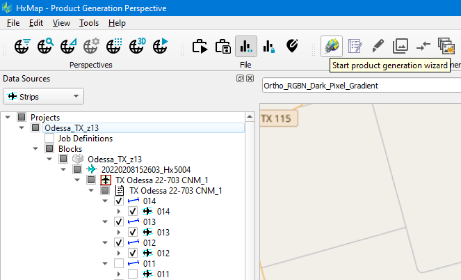
Once a selection is made the product generation wizard can be started.
Use a pre-defined product template
The first page of the wizard will show a list of all pre-defined product templates prepared by the user. To generate a pre-defined product, select it from the list and continue with the wizard.
Following wizard pages will show the template properties for informational purposes. These settings cannot be edited from within the product generation wizard.
The last page allows to specify project specific settings before submitting the job for processing.
Create a new product template
Besides the list of pre-defined product templates, a user has the option to prepare a new product template directly in the wizard. Definition of this new product is done by select pre-defined “Product Type”, “Radiometry” and “Output” specification templates.
To define a new product, select the “New Product…” option from the top of the list. The following wizard pages then allow to pick from the list of pre-defined specification templates prepared by the user. The wizard will show the parameter set for the selected specification template for informational purposes. These settings cannot be edited from within the product generation wizard.
Before showing the last project specification page, HxMap will display a dialog requiring the user to enter a name for the newly defined product template:
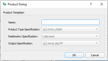
This newly generated product definition can later be edited under 'Edit' -> 'Templates' -> 'Products'.
Like generating a pre-defined product, the final step of the product generation wizard is to enter project specific settings.
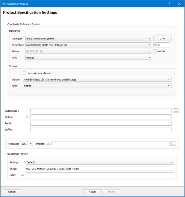
Project Specification Settings
Common Settings
Reference System
Coordinate System: This is the standard map projection selector used throughout the WFM. The user can set the specific map projection with optional parameters such as zone number in case the map projection is UTM.
Datum: Reference datum used for the map projection. Any datum defined in /etc/geodetic can be selected
Vertical Reference: Either ellipsoid or any geoidal reference defined in /etc/geodetic can be selected as a vertical reference
Horizontal Units: Can be either "metres", "u.s. survey feet" or "international feet" for cartesian coordinate systems or "degrees", "radians" or "gons" for polar coordinate systmes such as geographic projections
Vertical Units: Can be either "metres", "u.s. survey feet" or "international feet"
AOI: The user can specify an area of interest (AOI) which is stored as a polygon in a shapefile. When specified, only the area within the polygon will be processed for the output product.
Exclusions: The user can also specified areas that are to be excluded from processing. This is useful, for example, to avoid processing areas with water bodies or other areas that have no value to the user. The areas are stored as polygons within a shapefile.
Output Root: Defines a root directory that will contain all the output folders.
Output: Output folder name that is created in the output root directory. By default the folder has the same name as the product.
Prefix: Any string that is prepended to the product file names.
Suffix: Any string that is added to the end of product file names
Metadata: Allows to specify a template to be used for generating ISO metadata. (default for this option can be configured in the hxmap.ini)
File Naming: User can pick any pre-defined File Naming template, preview based on loaded session/ block data is given.
Aerial/ Ortho Product specific settings
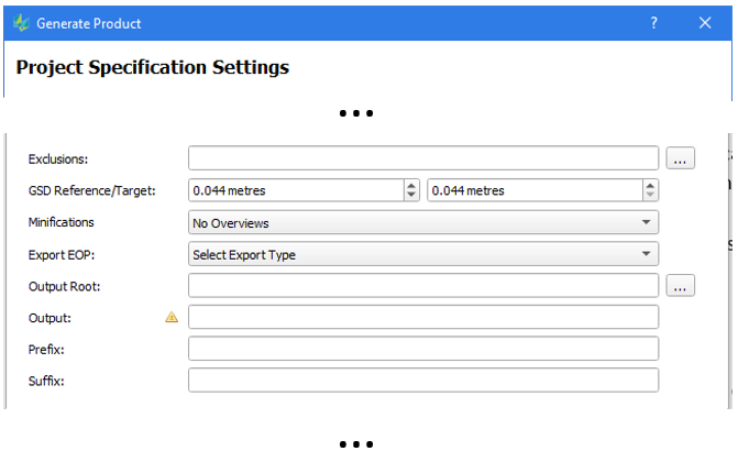
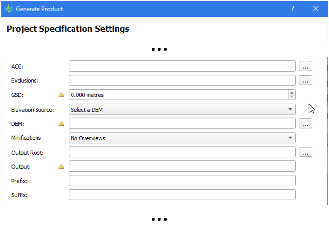
GSD:
ORTHO: The size of a pixel in object space, i.e. a GSD of 0.20 metres will create images where each pixel represents 20cm x 20cm on the ground.
AERIAL: Reference shows the computed average GSD of selected images, Target shows the desired output GSD. By default, both values are set to match a native (1:1) resolution. User may change the Target resolution only, so that HxMap auto-calculates the common scale factor for downsampling. In case the user wishes to apply a fixed scale factor, he may modify both, the reference and target, to specify the downsampling ratio. Changing the scaling factor to anything other than 1:1 will automatically check the EOP options so that updated EOP/IOP files are written with the resampled imagery.
Resampling aerial image can impact the image quality. This is especially the case for larger scaling factors.
Elevation Source: Defines the elevation source for the ORTHO product:
Select a DEM: User selects one existing DEM to cover the AOI. DEM data can be provided in *.img or *.tif format.
Global DEM: The product will use the elevation source as defined in the HxMap.ini file (see also GTopo section towards the end of this user guide)
DEM per take: Requires an existing DEM file (stored as .img or .tif) per input take.The user must specify a folder that contains the DEM files. Note that the filenames (without extension) must be identical to the take names.
DEM from block: Will use the DEM that was specified at block creation.
Constant height: User can set a fixed height about the vertical reference
Average Take Height: Product will compute an overall height based on all the input takes for the product.
In case of using Elevation GeoTiff files, assure to provide a tiled Tiff. Untiled/scanline Tiff files may produce artifacts
Minifications:
User can specify if image pyramids should be generator for the out product and if yes how they are stored:No overviews: No pyramids for the output images will be created
External overviews (SOCET SET): Pyramids are generated and stored as individual external files per pyramid level compatible with SOCET SET (*_2.tif, *_4.tif, *_8.tif, etc.)
Internal/Embedded overviews: Pyramids are generated and embedded in the output images
External overviews (OrthoVista): Pyramids are generated and stored as a single file compatible with OrthoVista (*.tif.pyr)
External overviews (ArcGIS): Pyramids are generated and as a single file compatible with ArcGIS (*.tif.ovr)
Export EOP
User can select between different ASCII output format for exterior orientation parameters incl. a link to the created images:GORI: file format to support the building finder workflow using the HxMap 3D Modeller bundle
True EOP (CSV): a text file providing exterior orientation parameter. In case of a selected map projection, the different scales for horizontal and vertical components are properly considered.
BestFit EOP for Map projection: a text file providing exterior orientation parameter. In case of a selected map projection, a Z scaling is applied to have an identical scaling in the horizontal and vertical component (single photo resection). This allows to treat the projected coordinate system as an LSR system and is required for various DPW.
3DModel Product specific settings
CityModeller (with building footprints) | BuildingFinder (without building footprints) |
|---|---|
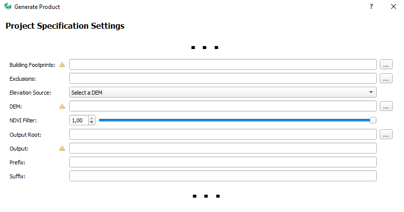 |  |
Building Footprints: The user must specify a building footprint file (polygons). TDC and SHP formats are supported. Every building footprint will be used to generate a building if applicable with building parts after splitting. The border of the building footprint is used to define the border of the building.
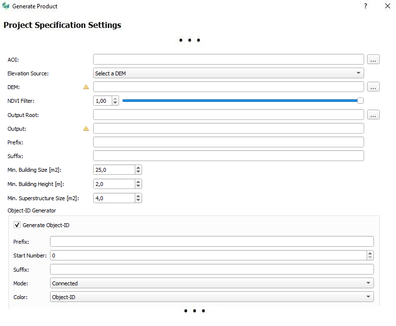
If one or more polygons on a special "Layer Number" define an AOI the user can run the building detection without footprints for these AOI by defining "BuildingFinder" as "Roof Type" for that "Layer Number". With this possibility 3D Model generation is able to run in "hybrid" mode - with and without building footprints.Without Building Footprints: Users can customize the minimum building size (default: 25.0 sqm), the minimum building height (default: 2.0 m), and the minimum size of superstructures (default: 4.0 sqm) before running the BuildingFinder
It is mandatory that the minimum superstructure size does not exceed the building size; otherwise, it will not be possible to start the job.
Exclusions: The user can also specify a file with footprints which should be excluded from processing (intersecting set of the Building Footprints). This is useful, for example, to avoid processing of already handmade buildings like special landmarks (television tower).
Elevation Source: Defines the elevation source for the 3DMODEL product: The lowest height within the building footprint area will be used for the ground height of the building.
Select a DEM: The user can select a DEM from IMG or TIF file. The DEM must cover all the building footprints!
Global DEM (SRTM or gTopo): The product will use the elevation source as defined in the HxMap.ini file. If both are defined SRTM will be used.
DEM from block: Will use the DEM that was specified at block creation.
Constant height: User can set a fixed height about the vertical reference
NDVI Filter: User can specify a threshold value for the exclusion (filtering) of vegetation points. The NDVI is calculated from the NIR (N) and RED (R) bands of the camera (RGBN, FCIR (NRG)).
1,00: No vegetation points will be filtered out.
The best value for vegetation filtering is depending from different factors. Normally a value between 0 and 0.5 can be used but has to be checked with a visualisation tool.
NOTE: There is a difference in the usage of the NDVI between the run with building footprints and the run without building footprints. During the run without building footprints (source: LiDAR) an intermediate step is the poinct cloud colorization. Therefore the NDVI can be used.
In the run with building footprints (source: LiDAR) there is NO colorization step and the NDVI value must be 1.0 (default)!
If the NDVI is set to a different value it cause a generation of LOD1 (default height) building model if the ingest was made before HxMap 3.4 From HxMap version 3.4 LOD2 buildings will be generated but the NDVI setting has no effect.
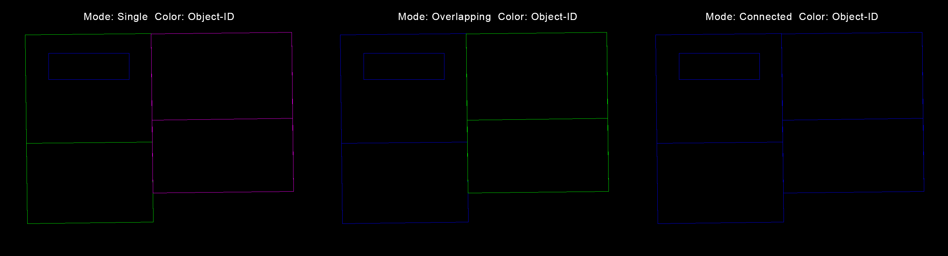
Object-ID Generator: User can specify how the Object-ID should be generated. Prefix and Suffix can contain strings and the start number is an integer value. The Mode (Connected, Overlapping, Single) defines which parts belong to one building. The Color (Object-ID, Quality, Unique) is generated by the given attribute.
TEXTURE Product specific settings
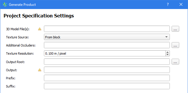
3D Model File(s): The user must specify one or more 3D Model file(s) in the TDC format.
Texture Source: Defines the source for the texturing process. Two options can be selected:
From block: Will use the image data and orientation which were specified at block creation.
From image folder: Will use the images and orientations (GORI) from the specified folder.
Additional Occluders: 3D Model files with geometry for occlusion detection e.g. buildings under construction. These geometry will not be textured but is used as additional geometry for occlusion detection.
Texture Resolution: Defines the resulting texture resolution in m/pixel. Normally the GSD of the image data.
LiDAR Product specific settings
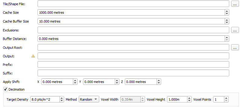
Tile/Shape File: defines the shapes that outlines the footprint of each output tile. The tile definition file projection is assumed to be in the output projection defined in the project settings for the run. The tile definition file can be:
a shape file containing multiple polygons used to define output boundaries for the tiles
the shape file must have an attribute named "MAPSHEET", it's value will be used to setup the file name for the tile. (So if the MAPSHEET attribute for a tile polygon contains "Tile_1" as the string stored, the tile file will be named Tile_1.<output ext>).
the shape file must have a corresponding projection file (.prj) describing its coordinate reference system
a text file containing one line per tile:
the format for defining a tile is: MAPSHEET UL_X UL_Y LR_X LR_Y
e.g. Ortho_RGB_0821132530103_0_349152_1312 11111.111 33333.333 22222.222 444444.444
the coordinate system of the text file is assumed to be the one used for Product Generation
Cache Size: size of a processing tile in [m]
Cache Buffer Size: Buffer the processing tile by this amount of [m]
Exclusions: Specify a file with polygon(s) to exclude the masked points from processing
Buffer distance: Buffer distance for the exclusion polygon(s) in [m]
Apply Shift (m): The user can specify a numeric value in meter, by which the point cloud product gets in X, Y, and Z dimension
Decimation: normalize point density in the output products
Target Density: Enter the target density of the output point cloud
Method: Choose one
Random: one point is picked randomly from each voxel
Voxel: point that is closest to the voxel 2D center is picked
Centroid: point that is closest to the group 3D centroid is picked
Edge: point representing feature edge is picked
Voxel Width: Computed based on Target Density
Voxel Height: Compute based on the minimum vertical separation capability of the lidar system
Voxel Points: required input for Random method. In case a value greater than 1 is chosen Voxel Width will be adapted. It can be used to normalize some small asymmetry in point spacing.
DEM Product specific settings

Water mask(s): based on a given shapefile, “Elevation” values are assigned to water areas in the output DEM (“Elevation” attribute defined as “float”, or shapefile type PolygonZ with valid Z values on vertices)
Buffer distance: buffer size for each Exclusions polygon
GSD: minimum cell size of an output DEM
Once the user hits the 'Finish' button on the last page of the wizard the product generation jobs are created and submitted for processing as discussed in Job Handling .