Defining Product Type Specification Templates
To edit or add a new product type specification, select "Product Types" from the menu as shown above and the following dialog will appear. There are a number of pre-defined product types already available. For a better overview you can use the Filter box to display products per specified type only.
To add any new product, select the green plus icon a new template is generated where the following parameters for the template can be set:
Name: assigns the entered name to the template. It is helpful to use a meaningful name that describes the product type
Type:
ORTHO: ortho-rectified image that is typically projected to an elevation source such as DEM or DSM
INFOCLOUD: digital surface model extracted from the imagery containing 3D points and image color information
AERIAL: standard frame aerial image
3DMODEL: 3D building vector data
TEXTURE: single textures per building face
LIDAR: group of 3D points in point cloud format
DEM: raster output that can be used as height reference for processing
Depending on product type, the dialog will present different settings to be defined by the user. The description of the individual settings is listed in the following section.
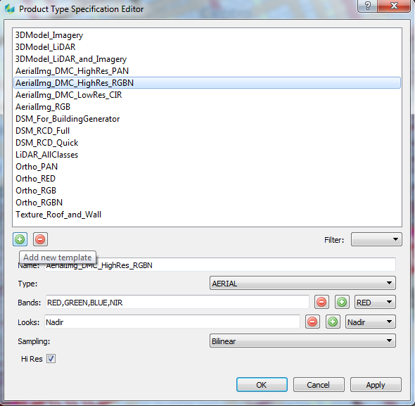
ORTHO or AERIAL products
The Definition of these Image related products requires the definition of:
Bands:
Band combination for the output product. Note that also the order of the bands is relevant for the output productBands are added by selecting the desired band and hitting the green plus icon
the last band in the list can be removed by hitting the red minus icon (the whole list can be cleared by hitting the red minus icon repeatedly)
In order to establish a definition for pan-sharpened DMC III image products, use the desired multispectral bands and enable the Hi Res checkbox to trigger pan-sharpening.
Sampling:
The resampling method for the output imagery can be specified. Currently supported are: bilinear and bicubicHi Res:
Select if a high resolution output image is desired. In case of DMC data, this option forces pan-sharpening to be applied. Note that by selecting this option the processing time can increase significantly
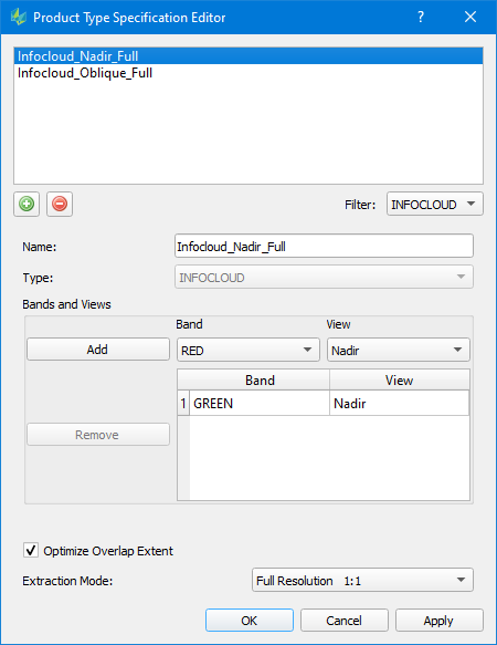
INFOCLOUD products
The Definition of an Infocloud product requires the definition of:
Bands and Views:
The user defines the combination of input images used for the point extraction by selecting the desired Band, View and Channel, which can be added via the “Add” button. The user can select a row and remove individual combination via the “Remove” button.RCD30/MFC150: it is recommended to use the green band for matching
DMC III: in order to achieve a high-resolution point cloud, select the PAN band for matching
Optimize Overlap Extent
Selecting this checkbox: SGM processing is optimized by using "most nadir" areas only, i.e. reducing potential overlap between stereo models to a minimum, both along and across strip. This results in increased performance yet providing full overall coverage. However, such an optimization can leave some smaller voids, e.g. in occluded areas; it is therefore discouraged to be used in downtown areas.Thinning Rate:
Select between MILD, MEDIUM or AGGRESSIVE. Determines the number of in-significant points that are removed from the point cloudExtraction Mode:
Selection range from 8:1 to 1:1. Determines the resolution used for matching. 8:1 will have the best performance but lower density whereas 1:1 will create the highest density results but will required longer processing time.
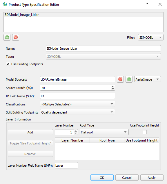
3D MODEL products
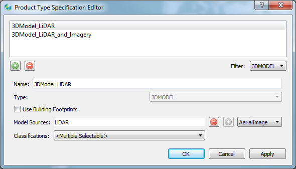
3D Models can be generated by using building footprints and different data sources (Lidar and/or Image from block and external sources) as well as without building footprints and a single data source.
The Definition of a 3D Model product with building footprints requires the definition of:
Use Building Footprints
Check the option, if the 3D Model process should use building footprintsModel Sources
AerialImage, LiDAR and ExternalData can be selected. The order defines the priority of the data for 3D modelling. LiDAR and AerialImage data will be used from the block definition. ExternalData (*.las/laz) can be used if airborne point clouds are available in a user defined folder.Source Switch (%)
This threshold is available if more than one Model Source is selected. The value is used to move to the next Model Source if the quality of a roof is worse (lower) than the given value.ID Field Name (SHP; Type: STRING)
If a shape file with building footprints (2D or 3D polygons) is the input for the process, the user must define which attribute from the shape file should be used as identifier for the building (case sensitive !). The content of the identifier field must be from type "string". Normally this value should be unique for all building footprints of a project. If not, all footprints with the same identifier will become one building after CityGML export.
If a tdc file with building footprints is the input for the process, this value has no influence because tdc files have an identifier by default.Classifications
Defines the classes of the input point cloud data to use for the building generation. This requires that the point cloud data has been classified beforehand.Split Building Footprints
Select which option shall be used for footprint splitting. “None”, “Always” or “Quality dependent”.
None: no split
Always: always split if possible
Quality dependent: Check the results of “None” and “Always” regarding quality and take the better oneLayer Dependent Adjustments
If external information about a building footprint are available they can be used for processing. Such information can be the roof type (Roof Type) and the height of the building footprint (Use Footprint Height). The Layer Number is used as "key" for these definitions.
e.g. All building footprints on Layer Number "2" are "Gable roofs" and the height of the building footprint (polygon) should be used as eaves height. (This information is often available if building footprints have been measured manually with photogrammetric software like the 3D Editor).Layer Number (SHP; Type: INTEGER)
Number of the layer identifierRoof Type
All possible roof types for the Layer Dependent Adjustment. These roof types will be forced to process.
Additionally there are two other options:
LOD1 roof - LOD1 objects (without a roof shape) will be generated
BuildingFinder: The polygon(s) on that layer will be used as AOI to run the 3D Model process without building footprints for that areaUse Footprint Height
If selected, the height of the building footprint polygon (z) will be used as height of the buildings eaveLayer Number Field Name (SHP)
If a shape file with building footprints is the input for the process, the user can define which attribute from the shape file is used as layer number information.
The Definition of a 3D Model product without building footprints requires the definition of:
Use Building Footprints
Uncheck the option, if the 3D Model process should not use building footprintsModel Sources
AerialImage, LiDAR or ExternalData can be selected. LiDAR and AerialImage data will be used from the block definition. ExternalData can be used if airborne point clouds are available in a user defined folder.
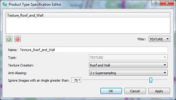
TEXTURE products
The definition of a Texture product requires:
Texture Creation
The user can select which part of a building should be textured (Roof, Wall, or both). A texture per face will be generated.Anti-Aliasing
Method to avoid jagged and pixelated edges within the textures.Ignore Images with an Angle greater than
Angle between the camera and the face. This angle can be set to avoid texturing of faces with a too steep angle (pixel smearing).
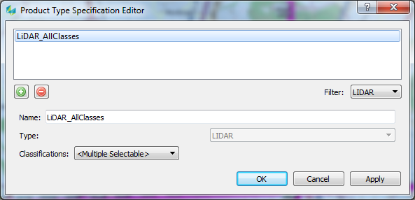
LIDAR products
The definition of a LIDAR product requires the definition of:
Name: Name of the template
Classifications: Classes to include when outputting the LiDAR product
During product generation HxMap will automatically renumber point returns based on the classes selected within this template. Renumbering of points will consider a buffer distance as defined in the hxmap.ini.
For a correct result, all points of a LiDAR pulse need to be contained within the buffered data. A larger buffer allows for more height variation in the data but will also lead to an increase in processing time.
Please see table below for determining the correct buffer distance:
Object Height | at 20° full FOV | at 30° full FOV | at 40° full FOV |
|---|---|---|---|
10m | 2m | 3m | 4m |
20m | 4m | 5m | 7m |
30m | 5m | 8m | 11m |
40m | 7m | 11m | 15m |
50m | 9m | 13m | 18m |
60m | 11m | 16m | 22m |
70m | 12m | 19m | 25m |
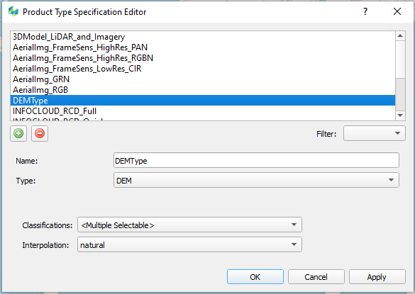
DEM products
The definition of a DEM product requires to specify:
Classifications: specify the classes of your point cloud that will be used as input for DEM generation
Interpolation: interpolation method to use for defining the DEM surface between points