Triangulation Run
Before you start a bundle block adjustment, verify all input data is available:
manual or automatic tie point measurement
ground control measurements (optional)
exterior information from processed GNSS/IMU trajectory information
Review the image data to be used during bundle block adjustment
All images in the triangulation project are assumed to be used in a bundle block adjustment, they are referred to be active. This is indicated by highlighting the individual images per take as "bold".
Active images are used in a bundle block adjustment in any case, independent on any filter which may have been applied to imagery e.g. for analysis.
If a user wishes to use a subset of images for bundle block adjustment, which is determined by an image filter, he can change the default activation status:
Use no filter.
Select the triangulation project, but do not check, and perform a right mouse-click
Select “Activate Images” > involved images are no longer highlighted as “Bold”, so they are inactive
Setup the desired filter, e.g. for Nadir images only
Select the triangulation project by using the check box and perform a right mouse-click
Select “Activate Images” > involved images are highlighted as “Bold”, so they are active
Bundle block adjustment will be executed on active images only
Review the standard deviation a-priori for ground control points
After importing ground control points, review the a-priori values set for those points.
The imported points are converted into the triangulation LSR, which can occasionally result in (slightly) different values for standard deviations compared to the import settings.
Review the standard deviation a-priori for point measurements
The standard deviation a-priori for point measurements reflects the accuracy of the individual image point measurements. In HxMap this value is per default set to 0.5 pixels.
However, a user can change that value on the Point tab also individually for different point groups, e.g. originating from different sensors or views. To do so, select and check the desired point group (e.g. all points of use "Tie"). Use the corresponding button from the top toolbar to set the desired standard deviation:
Confirm your settings via the OK button.
If you review the individual measurements for a sample tie point in the Points tab, the table indicates in the Orig.Std X/Y tab the assigned a-priori standard deviation values:
Set the standard deviation a-priori for exterior orientation parameter
The standard deviation a-priori for exterior orientation parameter is passed together with the trajectory during the data ingest step into the HxMap session. Therefore there is typically no need to set these values manually.
Exception may be, that
a user prefers to set a defined a-priori standard deviation
a user needs to define the a-priori standard deviation, when the internal data validation during bundle block adjustment invalidates a given value set and therefore reports an invalid image.
General Settings
General Bundle block adjustment settings are configured via View > Settings.
Triangulation Method: HxMap offers 3 modes for solving the least squares system in Triangulation Adjustment.
Mode 0 | Mode 1 | Mode 2 | |
|---|---|---|---|
Description | Rigorous method | Parallelized method + Final Inversion | Parallelized method |
Blunder Detection | full | simplified | simplified |
Parameter Std. Dev. | yes* | yes* | no |
Performance | slow | medium | fast |
Memory consumption | small | large | large |
Use Case | Camera misalignment calibration | Production where statistics are required in Triangulation report | Production without statistics in Triangulation report |
*Limited statistics provided when using hierarchical approach
Sigma-0: The initial standard deviation sigma-0 a priori provides the overall level of 'accuracy' for the triangulation. As such, it is used to scale the covariance matrix of the observations and, furthermore, it is required for meaningful blunder detection and elimination. The vast majority of observations consists of image point measurements, so the value of sigma-0 a priori needs to be chosen in the order of the standard deviations of these points. Therefore, it is to be set in [pixels].
It is very important to note that sigma-0 a priori does not define the standard deviation for image point measurements; these have to be set and, if required, adapted separately for individual points or groups of points, e.g., from different sensors.(see Points tab).
Maximum number of Iterations: Review and modify the number of iterations. The default value is set to 100, which is in average a reasonable number for most of the block configurations. Maximum number of iterations is 199. In general, more complex and/or weaker blocks will require more iterations than strong blocks with a regular block layout and a good and sufficient tie point distribution.
Find Blunders: Enables the automatic detection of blunders. If option "ImagePoints" is checked, the goal is to detect gross measuring errors. If option "Control Points" is checked, the goal is to detect defective control points, which do not fit in object space.
Blunder Detection Sensitivity: Set the sensitivity of the blunder test. The parameter setting influences the decision, whether an observation is a blunder or not. Default points to High
The sensitivity of the blunder detection is also influenced by the Sigma-0 a-priori setting. The bigger the value for Sigma-0 the less sensitive is the blunder detection. As blunders do affect triangulation results, sigma-0 a-posteriori will successively decrease during the iterative solution and blunder elimination process.
Max. remaining blunders: If the maximum number of remaining blunders is reached, the bundle block adjustment will stop iterating.
Datum Parameterization: With todays GPS receiver technology and mature GNSS post-processing procedures, the remaining systematic errors between GPS data and photogrammetric data is reduced to a datum transformation. The HxMap bundle block adjustment allows to solve for a set of 7 datum transformation parameters that describe a 3D similarity transformation. These parameter are sufficient to compensate for remaining systematics. In any case Ground control measurements are required to model datum transformation parameters.
In a first step, select the datum model:
None: Datum transformation parameter will not be determined. Select this option, if there are no ground control points available. In that case BBA is performed based on GPS/INS data.
Session: Select this option in case the triangulation block consists of image takes which are captured during multiple flight sessions. It needs sufficient Ground Control measurements per area of each Session, so that multiple sets of datum parameters can be estimated.
Project: Select this option to estimate the overall datum transformation of the triangulation project
Depending on the chosen datum model, the user can select if one, several or all datum parameters are determined during the adjustment. This also has an impact on the number of required ground control points. If the goal is to determine the datum translation in XY and Z, one full ground control can serve as a minimum configuration. The determination of the remaining Rotation and Scale parameter requires a minimum of two planar and one vertical ground control point. In any case, be aware that a higher number of ground control points is recommended in order to provide redundancy.
The selection of the datum parameters allows three modes:
do not use | uncheck | ||
use | check | ||
auto use | In case "Auto Use" is enabled, the adjustment process verifies automatically, if the minimum set of ground control information is available to determine the marked datum parameter. If so, respective datum parameters will be estimated. |
IMU Parameterization: The observed rotation angles introduced in HxMap are delivered by the IMU referencing the axes of the IMU gyros, while the orientation angles used in photogrammetry refer to a camera coordinate system. Both systems are usually not parallel, so that the calculation of a misalignment becomes necessary. If not already known from a previous boresight calibration, HxMap allows determining the misalignment via the IMU parameterization.
To do so, check one of the following options:
None: IMU Misalignment parameter will not be determined
Sensor: Select this option in case the block has the configuration of allowing IMU parameterization, which is containing at least two overlapping strips flown from opposite directions
Session: Select this option, in case the triangulation block consists of image takes which are captured with multiple flight sessions. IMU parameter are determined individually per session, each containing at least two overlapping strips flown from opposite directions
Strip: Select this option, in case the Bundle Block adjustment indicates remaining systematic effects in the IMU angles. This option introduces further degrees of freedom, as it tries to determine angle offsets on a per-strip basis. This may be caused by a systematic non-mechanical misalignment when there are re-flown strips added to the project, or the remaining IMU systematic cannot be compensated by other options. Therefore be advised to use the option with care.
Calibration: The Calibration section allows to enable the estimation of intrinsic camera parameters as there are focal length and principal point (PPA). The general assumption is, that these parameters are provided with the camera calibration and behave stable between calibration cycles. However, the physical conditions during a flight may vary from the conditions during the calibration, which may lead to small variations of the camera parameters.
Enable the camera calibration parameter, if you suspect remaining systematic errors even after you verified that your triangulation project has been cleaned up from blunders and other system parameters such as Datum or IMU parameterization did not fully model all systematic errors. If this holds true, it may be worth to enable the use of camera calibration parameters. You may want to enable each parameter separately to evaluate the influence on the adjustment results.
Free: Parameter will be estimated with a large standard deviation applied to its initial value, i.e. practically "free".
Constrained: Parameter will estimated but constrained to its initial value.
Locked: Parameter is fix and will not be estimated.
The use of the camera calibration parameter is justified, if the corresponding BBA run shows a reduction in the random errors. The values for Sigma-0 and ground control residuals are expected to reduce, but also the systematic part of the residuals for GPS and IMU observations may decrease or even be eliminated.
In any case make sure, that the triangulation project is well covered with tie points in order to obtain reliable results.
Be aware, that e.g. estimation of focal length requires also ground control information and reliable GPS data (or different flying heights).
RCD30 Penta 80/150 triangulation process has differences compared to Penta 50/80. There is high correlation for 156 mm lens cameras between the IMU Misalignment and PPA parameters. Thus users should not switch 'on' the estimation of PPA (x0 and y0) for the 156 mm lens cameras in the triangulation process.
Variance Components: The variance components reflect, if certain types of observations (here the GNSS and IMU observations) are weighted correctly in respect to other types of observations. The weight for the observation is derived from its standard deviation a-priori. For GNSS/IMU observations the standard deviation a-priori is derived from the GNSS/INS post-processing solution, which is usually quite optimistic and therefore requires a scaling factor to be applied to guarantee that the weight relation among these and all other observations is correct. You may want to leave the default scale parameter for the initial bundle block adjustment runs, before you adapt them based on the calculated variance components as reported from the adjustment.
Default values:
A correct weight relation is given, when the resulting variance component factor for a particular observation type is close to 1. The variance component will be less than 1 if the standard deviation a priori is set too large. The variance component will be greater than 1 if the standard deviation a priori is set too
small. Based on this rule, adapt the scale factors in order to reduce or increase the standard deviation a priori for GNSS/IMU observations.
Launching the Bundle Block Adjustment
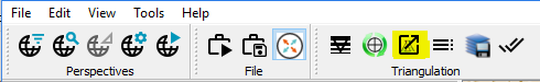
A bundle block adjustment is performed each time you use the "Run Triangulation Adjustment" button:
A progress bar indicates, when the adjustment run has been finished and summarizes the number of iterations needed to solve as well as the resulting sigma-0 a posteriori.
Use the arrow buttons to review the summary of each iteration individually. The "Detail" button will expand the dialog to give some additional key statistics per iteration:
The bundle block adjustment run writes its results internally into the AT project in a "Context" subfolder.
Bundle Block Adjustment on oblique datasets
Oblique datasets produced by a Leica CityMapper come with five times the amount of image data compared to regular nadir projects. This in combination with a high overlap between the individual takes and flight lines plus a smaller footprint compared to large frame systems, causes a huge amount of images and observations to be in place for a single flight project. If handled in a single AT project, the classic bundle block adjustment approach easily hits the limits in terms of performance, so that an approach to simplify the triangulation run has been introduced.
Hierarchical approach
An oblique triangulation project that is run simultaneously for all views presumably provides the best overall result but will get too large to handle at some point and needs to be split. For the hierarchical triangulation, all images in the nadir view are triangulated in a first run. Subsequent runs adjust each oblique view to it. To achieve this we make use of so called connection points. These are tie points from the nadir triangulation which are then introduced as control points in the triangulation runs of other views. By introducing this method, a significant performance gain is achieved.
It is important to know, that the approach does not support the estimation of a misalignment, nor the estimation of camera calibration parameter. Due to that fact, make sure that the involved sessions have a valid misalignment applied at ingest time. If you are not sure, please start the HxMap workflow with a small sub-project only, which can be used to determine a potential misalignment, before starting production on a very large project.
The hierarchical adjustment approach can be picked after launching the bundle block adjustment by using the "Run Triangulation Adjustment" button. It will trigger the following dialog:
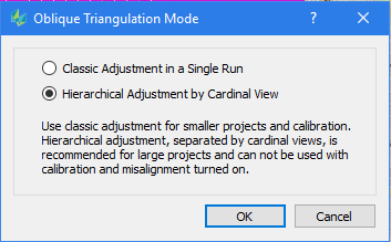
Pick, whether you wish to proceed with a simultaneous bundle block adjustment using all view (Classic Adjustment) or you wish to proceed with the hierarchical adjustment.
Once the triangulation run has been started, the progress bar informs about the overall status and the progress of the subsequent adjustment runs.