LiDAR misalignment calibration
After each sensor installation an IMU-misalignment re-estimation should be done in order to update the values of the Roll, Pitch and Heading parameters. Other calibration parameters should not be updated
Trajectory
The quality of the processed trajectory file is particularly important during a LiDAR calibration. It is recommended to have a GNSS base station close to the calibration area. Aircraft should not be more than 30 km away from the basestation during the calibration flight.
Using PPP, Omnistar corrections or similar reduces the accuracy of the trajectory and should be avoided during a calibration flight.
GNSS antenna lever arms needs to be well defined and should be measured with high precision.
Area Selection
The calibration is looking for planar surfaces. For optimal result the calibration needs surfaces that are tilted in different directions.
Optimal is to use an area with large buildings; warehouses, hangars, sports arenas etc. with preferably irregular shaped or ridged roofs. Ground level needs to be well defined, good samples are tarmac, gravel, short grass,sand etc. Keep in mind, that trees, cultivated crops, high undergrowth and other vegetation can give a big spread in the point cloud.
It is preferred to use an area containing Ground Control Points (GCP’s) during the Quality Control, therefore a few GCP’s are recommended within the calibration area, which are measured at flat hard surfaces like parking lots.
Ground Control Points
The LiDAR Calibration doesn't use ground control points, but GCPs should be used in the QC step to check the absolute horizontal and vertical accuracy. Ground control points should be collected on a flat surface (parking lot, roof).
Flight Pattern for Misalignment Calibration
It is recommended to perform a set of lines to be used for the calibration, followed by a set of lines used to verify the computed results.
Flight pattern to use depends on the LiDAR sensor to calibrate and are described in the sensor-specific part of the documentation: Sensor Specific Documentation
Calibration Run
The following is the procedure for running a calibration for all LiDAR sesnors:
Run HxMap Workflow manager and pick the Session Perspective
Add a raw session.
Use the “Capture->Type: LiDAR” filter to remove any Image footprints so only the LiDAR footprints can be seen on the central map.
Select an area on the central map that you want to use for calibration as described in https://hexagonmi.atlassian.net/wiki/spaces/HEXMAPDOC/pages/44131169726/Working+with+AOI+polygons#Selecting-AOI-polygons-for-processing . If needed use the Edit menu to "Clear Selection Polygon".
Press the "Ingest Session" and the Ingest Dialog will come up.
Pick the respective L0 Calibration product type based on the sensor type
Fill out the rest of the parameters on the Ingest wizard
Run the ingest and wait till the session is created.
Switch to the QC perspective and let the new processed session load into the map.
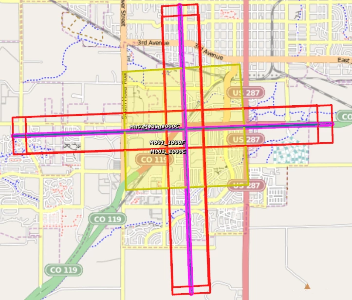
Select the four calibration lines. The entire lines are not needed but the selected area should extend the line crossing area in the middle as in the figure below.

Start LiDAR calibration from Tools→Run Lidar Calibration
Wait for the calibration to run. It will output some feedback into the progress window.
After it completes successfully it should report some statistical values and write a new calibration into the intermediate/cam directory of the session.
Apply Calibration
Based on the need there are two ways to apply the results of a calibration
Global Repository: one option is to copy the result from the calibration to the global repository if the calibration is expected to hold across flights for the specific sensor and installation
Project Calibration: is using the results from the selected AOI to the entire flight
The global option will be a simple file copy step with renaming to increase the version and the ingest process is done as before. The following steps show the second option of applying the project calibration to using a final ingest of the raw data:
Switch back to the Session Perspective
Select the raw session to ingest again. This time pick all strips you want and whether you want Images or Not.
Press the "Ingest Session" button and the Ingest Dialog will come up.
Select the SOL file for the trajectory
Press the "Project Calibration" button and then pick the Calibration from the calibrated session's "intermediate/cam" folder.
Make sure the Calibration is now showing the Project calibration
Make sure to pick a new output session directory for the full session run.
Run the ingest and wait till the session is finished.
Check the QA plots for the circular lines.