Hyperion2
The Hyperion2 LiDAR module is part of the TerrainMapper-1/2 as well as CityMapper-2 systems.
Gated vs Ungated Mode
Hyperion2 sensors can be operated in either gated or ungated mode.
Gated Mode: Data is only collected in a single MPiA zone. The extend of this window (or range gate) can be seen in MissionPro in the AeroPlan tab. If data was collected outside the planned MPiA zone, then the data will be misplaced in height (wrong MPiA zone).
Ungated Mode: In ungated mode, data is collected without restrictions and the correct MPiA zone for every point is determined during ingest. The algorithm for determining the correct zone will use multiple zones above/below neighboring points. If data was collected using a high pulse repetition frequency (PRF) the resulting zones will be very small. It can therefore happen that even though HxMap evaluates multiple zones, the point might be located outside the evaluation window. In cities where large elevation jumps (e.g. skyriser buildings) are expected, it is therefore recommended to lower the PRF during acquisition which will extend the evaluation window (as all individual zones will become bigger)
Scan Pattern
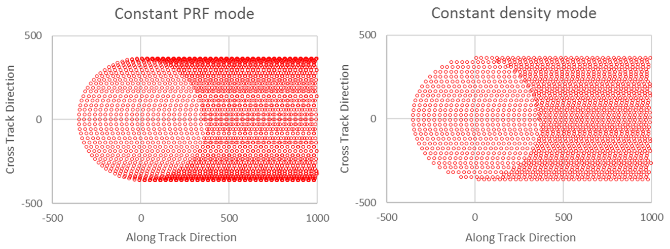
By default, Hyperion-2 sensors will use a circular scan pattern. When operating the sensor at a constant PRF, this means that the resulting point density at the edge of the strip will be higher than the center of the strip. This is because the sensor movement at the edge is along flight direction while in the center it is across flight direction. Customer that want to achieve a uniform point density can choose to operate the sensor in constant-density mode. This dynamically adjust the PRF along the rotation which produces a point cloud with equal point distribution.

In addition to the circular scan pattern, Hyperion-2 can also be operated in a flower pattern. This pattern is mainly used for calibration and should not be used for production flights.
Sensor Misalignment Pattern
Lines for misalignment calibration
Double cross flown at 2000 meters AGL, 4 total strips
Each line of the cross flown twice, in opposite directions
One direction in flower mode, and the opposite direction in circle mode
Pulse and scan rates as shown in the table, all lines are flown in gated mode
Differential GNSS with baseline < 30km
Direction | Scan Pattern | PRF (kHz) | Scan Rate (Hz) | SNR | Threshold |
|---|---|---|---|---|---|
N → S or S → N | Circular | AutoAdjust | AutoAdjust | 12 | 150 |
Opposite to above | Flower | AutoAdjust | AutoAdjust | 7.1 | 150 |
E → W or W → E | Circular | AutoAdjust | AutoAdjust | 12 | 150 |
Opposite to above | Flower | AutoAdjust | AutoAdjust | 7.1 | 150 |
All lines flown at 2000m AGL, 40deg FOV, 5-10km line length, in gated mode and with 6-7 MPiA zones | |||||
Lines for verification
Flown in same mission as estimation lines
Single line at 2000 meters AGL, 2 total strips
The line is flown twice, in opposite directions with a side overlap >20%
Both directions in circle mode
Pulse and scan rates as shown in the table, either gated or gateless
Lines from real project are also OK if they are flown after the cross
Using gated mode:
Direction | Scan Pattern | PRF (kHz) | Scan Rate (Hz) | SNR | Threshold |
|---|---|---|---|---|---|
N → S or S → N | Circular | AutoAdjust | AutoAdjust | 12 | 150 |
Opposite to above | Circular | AutoAdjust | AutoAdjust | 12 | 150 |
All lines flown at 2000m AGL, 40deg FOV, 5-10km line length, in gated mode and with 6-7 MPiA zones | |||||
Using ungated mode:
Direction | Scan Pattern | PRF (kHz) | Scan Rate (Hz) | SNR | Threshold |
|---|---|---|---|---|---|
N → S or S → N | Circular | AutoAdjust | AutoAdjust | 12 | 150 |
Opposite to above | Circular | AutoAdjust | AutoAdjust | 12 | 150 |
All lines flown at 2000m AGL, 40deg FOV, 5-10km line length, in ungated mode | |||||