3D editing functionality
If the geometry of an object was changed the system will automatically set the “Modified” flag and the current “Modified Date” property. Exceptions are the functions “Roof Only” and “Intersection with Terrain”.
Undo/Redo

All edit steps can be made undone and redone. By default 20 undo steps are possible. The number of max. undo steps can be configured in the HxMap.ini [3DEditor] section.
Changing the object layer
The assigned layer of a (selected) 3D object is visible in the
Object List View
Layers View
Properties Window
In the Object List View, the users can sort the 3D objects by layer. Toggling the head of the Layer column will change the subsequent lines from de- to ascending order and vice versa.
HxMap provides the functionality to select one or multiple 3D objects and change its/their layer by
Manual modification in the Properties Window
Using the right mouse button > Change Layer (is only available when at least one object is selected)
Using the drop-down menu > Edit > Change Layer (can only be selected when at least one object is selected)
The (new) layer will be updated in the Object List View and the Layers View. The change will not trigger the "Modified" flag in the Properties Window.
It is possible to un-/check the 3D Model layer(s) in the Layers Window, so, the corresponding object(s) will be in-/visible in the Viewers.
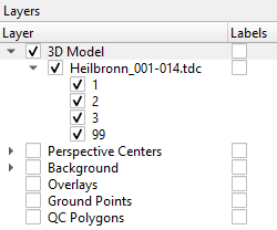
Any selection on hidden objects will be removed to avoid unexpected changes on not visible objects. Also the Edit mode status of hidden objects is repealed.
Object Edit mode

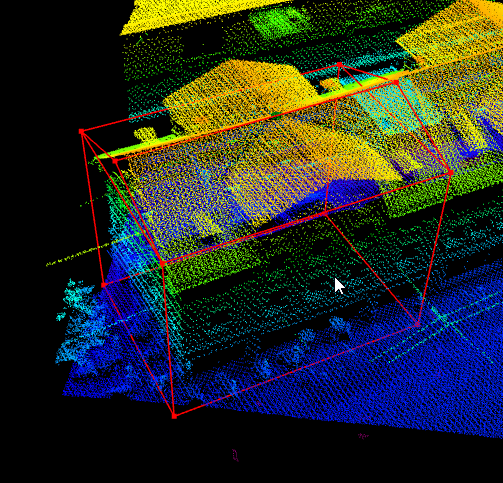
HxMap allows to interactively edit the geometry of a building. To activate the edit mode, press the "Edit" button in the toolbar.
Once activated, user can drag and drop vertices of the selected building, which is highlighted in red once the mouse hovers over it.
Moving points can destroy planarity of related roof surfaces! Please run the planarity check.
Moving points in 2D:
In the case where two points are on top of each other (e.g. building edge/corner), HxMap will move the upper point.
To move the lower (footprint) point, press the Alt-Key and drag and drop the point.
Points are moved on a horizontal plane
Moving points in 3D:
In 3D only the selected point is moved
Points are moved in 3D space instead of the horizontal plane
Moving points in stereo view:
In stereo view the points are moved on a horizontal plane
Vertex selection
For further editing of vertices it is useful to select them upfront. This is possible like for other selections with a left mouse click and drawing a rectangle or polygon with pressed SHIFT key. With a pressed CTRL key the vertices can be added or removed from selection.
Vertex deletion
If an vertex is selected it can be deleted by using the RMB (Right Mouse Button) context menu or the DEL key. Only redundant vertices can be deleted from a building object.
Copy and Paste height information from a point/vertex
If one or more vertices are selected the copy and paste height functionality is available on the RMB context menu to take over height information from one object to another.
Splitting a face
If two (not adjoined) vertices of a roof face are selected it is possible to split the surface into two pieces.
Inserting additional node points

In addition to moving existing points, additional points can be added. The insert node mode can be activated in the toolbar.
To add additional nodes on an existing edge, first position the cursor over the edge line. The cursor will then change into a triangle in the center of the edge or into an X at any other position on the line. With a single mouse click the additional node is then inserted.
HxMap will automatically create a ridge and footprint node at given location.
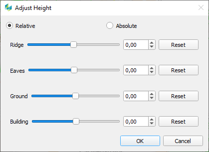
Adjusting object heights

Select the objects you want to adjust in the map window (or one of the other windows). In the Edit toolbar, press the "Adjust Height" button to open the dialog box shown below:
Adjust object ridge
Instead of moving individual vertices, HxMap allows to shift and rotate the ridge of a building.
To shift the ridge:
right-click an object and select: Adjust ridge > Move ridge
use the slider in the dialog box to move the ridge in parallel direction to either side of the current position
To rotate the ridge:
right-click an object and select: Adjust ridge > Rotate ridge
HxMap will automatically rotate the ridge by 90 degrees and adjust the ridge points accordingly
Move objects or object parts

Select the objects you want to move in the map window (or one of the other windows). In the Edit toolbar, press the "Move Object (Part)" button or press F6 to open the dialog box shown below:
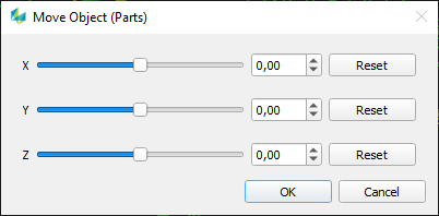
Moving any of these sliders will move the selected objects in the X, Y or Z direction. The input field allow entering exact relative values. Using the arrow left/right keys changes the values in steps of 0.1 and using the page up/down keys changes the values in steps of 1.0.
If the Edit mode (E) is active also selected vertices can be moved in a similar way. Additionally it is possible to use the combination CTRL+LeftMouse to move objects or selected vertices. If an anchor point (white vertex marker) is visible before starting the move operation it is also possible to use the snapping functions.
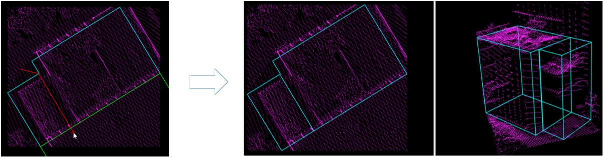
Cut Objects

It may be required to cut one object into multiple ones in order to properly model the building. To do so, select the desired object as described above and launch the split functionality either via the Edit Toolbar, the pocket menu or short key “C”. The cut function requires to draw a line at the intended cut. Start and end point of this line can either be placed outside of the object (see sample below) or via the snap function directly on the outline of the selected object. To finish drawing, double-click when placing the end point.
Sample:
Copy and Paste Objects
HxMap allows to copy and paste all selected objects (if Edit mode is not active).
Copying objects can be executed via
Right-clicking into the view window (drop-down list opens > Copy Object(s))
Using the shortcut Ctrl+C
Using the menu bar: Edit > Copy Object(s)
Pasting objects can be executed via
Right-clicking into the view window (drop-down list opens > Paste Object(s))
Using the shortcut Ctrl+V
The users can define an anchor point by hovering with the mouse arrow over a point of the source object(s) before copying. If no anchor point is defined the lower left corner (x, y) of the bounding rectangle of the selected object(s) functions as an anchor point.
The copied object(s) can be snapped to an existing (target) object by hovering with the mouse arrow over a point of the target object before pasting.
The following attributes are taken over to the new object(s):
Object ID
Type
Color
Layer
Quality
For each pasted object, a new GUID is generated.
Intersection with the elevation model (DEM)
After capturing a new roof it will be automatically intersected with the elevation model defined in the project.
The user can also force a new intersection with the DEM.
Edit → Intersection → Intersection with Terrain will intersect all objects with the terrain.
Selecting one or more objects and use the content menu (right-click) “Intersection with Terrain” the selected object(s) only will be intersected with the terrain.
If the elevation model height is configured to be taken from a TIF file, the heights are visualized in the 3D view window. Otherwise a global height model is used.
Depending on the HxMap.ini settings the intersection will be done to the lowest height of all object points or to the surface (every ground point will get it’s individual height).
By default the intersection by Object-ID is set to true in the HxMap.ini. Therewith all ground points from an object with the same Object-ID will get the same lowest ground height.
Superstructures will be intersected to the underlaying roofs (and not to the ground).
Layers which shall not be intersected can be defined as well in the HxMap.ini.
Intersection with the building footprint
If building footprints are added to the project and the Object-ID of the building and the corresponding footprint match it is possible by pressing the “Q” key to get a preview of a footprint intersection (cut-off/enlargement) result. The footprint intersection functionality is part of a command line executable.
The HxMap.ini setting “VertexDisplacementThreshold” is a threshold value for the footprint intersection process. (Default: 0.03 m). This allows a vertex to be distant to the footprint by the given value.
If an object can not be intersected with the command line executable (editor3dtool --intersectFootprint) a flat roof will be generated the Quality property is reset to “0” and the ModelSource becomes the value “Fallback”.
Deleting of objects

A user finds different options to delete an object:
by pressing the toolbar button "Delete object"
through the context menu on selected objects
by pressing the delete key on the keyboard
In any of these cases, all selected objects will be deleted from the geometry (tdc) file.
Convert roof types
If a wrong roof type has been detected or defined, a user has the option to convert the roof to another roof type.
To do so, right-click on selected object(s) and select "convert roof to" and select the new roof type from the options in the list.
HxMap will try to convert all selected roofs. Possible conversions will depend on the original roof type and HxMap will skip converting roofs if conversion is not possible.
Snapping functionality
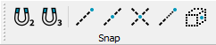
Snapping is possible in 2D and 3D space to other point objects, lines, crossing lines, imaginary extended lines and faces, but also to overlay layers of type TDC and Shape.
It is always a combination of space and object needed to have the snapping activated. Keyboard shortcuts help to quickly change the functionality.
Small cross (point) or triangle (center) widgets indicate the correct snapping position.
Check the planarity of an object
HxMap allows checking if the surface geometry of a building object is planar or not.
Apply the feature by
Either right-clicking into the viewer: Check Planarity → Check All/Check Selected
Or using the menu bar: Edit → Check Planarity → Check All/Check Selected
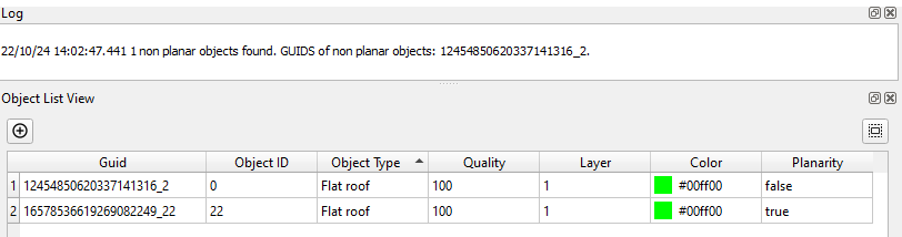
The attribute (true/false) will be displayed in the Object List View.
The GUIDs of non-planar objects will be displayed in the Log.
Customize the threshold by adapting the parameter “PlanarityCheckThreshold” in the HxMap.ini file (default setting = 0.01 m).