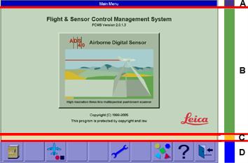
General screen layout
|
|
|
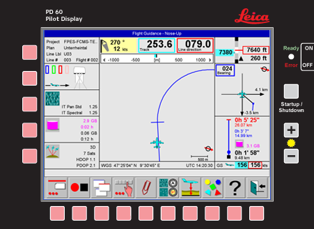
Touchscreen interface on OC61 Operator Console
On the bottom of the screen of the OC61 Operator Console display, a bar with a maximum of 10 large touch sensitive icons is displayed. This is the main touch interface area on the screen. All user interaction for workflow commands, activities, change of views and button changes can be performed by touching the appropriate icon on the tool bar.
Beside the tool bar, additional areas on the screen are touch sensitive in some views. These additional touch sensitive areas enable user input shortcuts.
Examples:
-
to select an input field the user can touch the input area on the view
-
to display another view the user can touch the desired TAB on the screen
-
to show status of a sub-device the user can touch the corresponding control on the screen.
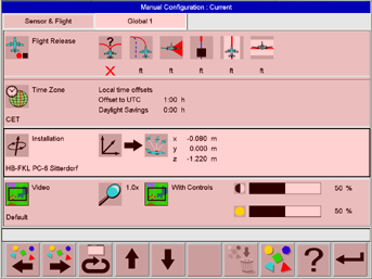
Examples of touchscreen fields in different views
As an alternative to pressing the 
As an alternative to pressing the 

As an alternative to pressing the 

To display status views of various subsystems touch the corresponding control. For example the 
Alternatively the selection can be made by using the icons on the toolbar. For example the 
Direct selection by touch and pan of graphics
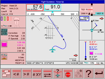
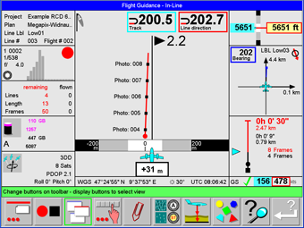
Selection of flight lines by touch is possible in the graphics in the North-Up and in the In-flight Evaluation view. Selection by touch is also possible in listings, such as Configurations. The graphics in the North-Up and in the In-flight Evaluation view can be panned by touching the graphics and dragging it with the finger.
Hard key interface on PD61 Pilot Display
On the bottom of the housing of the PD61 Pilot Display, there are 10 hardware keys are placed below the screen. This is the main interface. All user interaction for workflow commands, activities, change of views and button changes can be performed by touching the appropriate hardware key located below the icon displayed on the Leica FlightPro tool bar.
Additional hardware keys are located on the housing on the left side of the screen. These keys enable user input shortcuts. For example In 1st level help mode the key located by the control can be confirmed to display the 1st level help text in the status line.
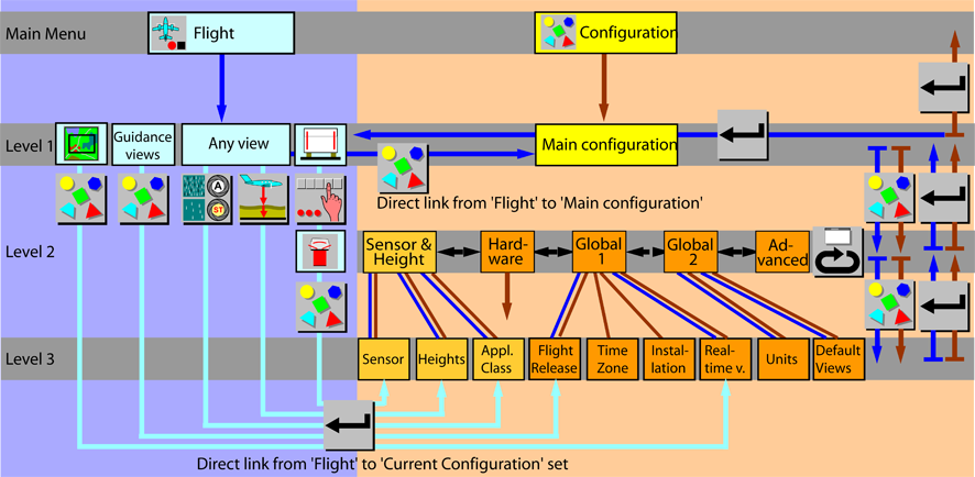
Navigation within the menu tree
The user interface is designed to minimize the complexity of the system. Therefore, the tasks are organized into just a few menus and each menu tree has only a few levels. The menu tree is just the internal skeleton of the software. To use the system, the user has not necessarily to memorize it. The user interface allows for quick navigation within the menu tree.
-
In menu Flight, hot-key buttons allow for fast changes of views.
-
In menu Flight, direct links between nodes in Flight to Configuration are implemented.
Navigation within the menu tree in flight execution
During fight execution different processes (sub-programs) are running simultaneously. These different processes control:
-
Sensor and sensor sub-systems such as GNSS/IMU, Mount, etc.
-
Flight guidance based on GNSS and flight plan
-
Thumbnail-Images displayed on the real-time view
-
Project management - In-flight evaluation
Status of each process is shown on the operator interface. Therefore, the user can select different views:
-
Sensor status
-
Flight guidance - Nose-up, North-up, In-line, 3D view
-
Real-time view
-
In-flight evaluation
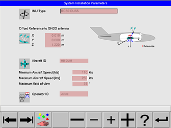
From the sensor status view other views can be selected showing the status of sensor sub-systems such as GNSS/IMU or Mass Memory.
Select the 
Select the 
Navigation within the menu tree to reach Configuration
Menu Configuration
The configuration allows for the quick adaptation of the system for different applications. In menu Configuration the user can predefine configuration sets as required for the various applications. Unlike in menu Flight the sub-systems like sensor or mount are not in a powered state in menu Configuration.
Menu Flight
Links from the flight menu tree to the configuration menu tree are implemented to enable quick changes of the system configuration during flight without the need to quit Flight and select Configuration from the Leica FlightPro main menu. Unlike in menu Configuration the sub-systems like GNSS/IMU, sensor and mount are in a powered state and initialized in menu Flight. Therefore the global parameter Installation cannot be changed. Because changing the installation parameters requires re-initialization, which is performed by the system only during the start-up of Flight Execution.
Online help
Online help can be selected from any menu level at any time. The 'Help' button is part of the button bar on each view. The online help facility consists of two levels:
-
First help level gives a short description of each button on the status line.
-
Second help level allows browsing of Leica RCD30 documentation.
Note: Entering help does not interrupt operation of the sensor. For example, if the recording of data was activated, this status remains the same even if the user enters help.
Entering help does not interrupt operation of the sensor. For example, if the recording of data was activated, this status remains the same even if the user enters help.
First help level - short description
Select 
The Green background of the status line indicates that first help level is activated. In this mode, just touch any button or control to get a short description of it on the status line.
Select 
Select 
Second help level - System documentation
Entering second level help is only possible from first level help. It does not interrupt operation of the sensor. For example, if the recording of data was activated, this status remains the same even if the user enters second level help.
Select
Select 

Select 

Select 

Select 
Select