The 3D Advanced module enables the user to create 3D Textured Mesh and True Ortho products from HxMap’s Product Generation Perspective. The following guide provides a quick start to installation and use of the module.
System Requirements
3D Advanced module requires GPU for certain compute tasks of the meshing pipeline. Other than the GPU, machine requirements are the same as described in System Requirements.
GPU Requirement for 3D Advanced
-
Manufacturer: NVIDIA
-
Model: Must support NVIDIA CUDA Runtime at CUDA compute capability level 6.0 or higher
-
See https://developer.nvidia.com/cuda-gpus for a lookup of capability level of various NVIDIA GPUs
Installation
3D Advanced module is packaged in four additional installer executables Place the installers in the same directory as the HxMap Full Installer, and run the Full Installer. 3D Advanced installers will be automatically detected and included in the installation. It is not possible to run 3D Advanced module installation separate from HxMap Full Installer. Distributed installation can be achieved following the instructions in Distributed HxMap deployment. Nodes should be configured to advertise their GPU as described in GPU Resource .
Workflow
The reconstruction process to generate 3D textured mesh and true ortho depends on accurate geometry and radiometry to achieve good results. The required workflow for 3D Advanced Product Generation is:
-
Triangulate Images
-
Match Lidar
-
Run Blockwide Radiometry
-
Run Product Generation
-
QC and Edit Products
When the 3D Advanced module is installed, a new Product Type will be available, ‘MESH’. This Product Type will automatically create both the 3D textured mesh in Cesium 3D Tiles format and the true ortho in GeoTIFF format. Set the Radiometry template for the MESH Product to Frame Sense Full in order to take advantage of the Blockwide Radiometry result.
In the Product Generation wizard Project Specification page for MESH Product Type, there are two key settings.
|
Setting |
Description |
|---|---|
|
AOI |
An AOI should be given for each product generation run. It will be used as the limit for the 3D reconstruction process and should have full coverage in all image views and lidar for proper reconstruction and texturing results. |
|
Target Dilution |
The mesh texture quality and run time depend on density of input images. Target Dilution parameter may be used to reduce planned image density to an optimal value for mesh generation. Image density is quantified by the flight plan value Tau calculated in MissionPro and is a function of forward and side overlap together with image area. Recommended Tau values for 3D Advanced with nadir + obliques in different landscapes are:
Plan with the recommended Tau value in MissionPro for the most economical flight plan to support 3D Advanced product generation. In case a higher Tau value is needed to support other product specifications in the project, use Target Dilution to reduce the image input for the MESH product type. The list below shows the dilution strategies available, choose the dilution strategy will reduce Tau closest to the recommended value without going below it.
For 3D Advanced with nadir images only, a Tau value of 25 is recommended for all landscapes, generally no dilution is necessary. Note that vertical facades may not be optimally textured with nadir views. |
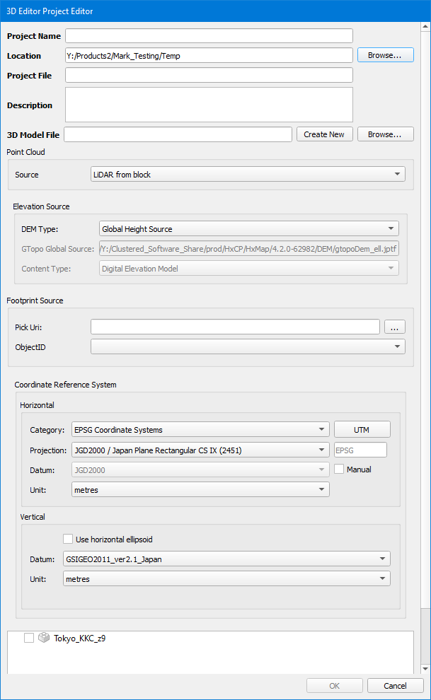
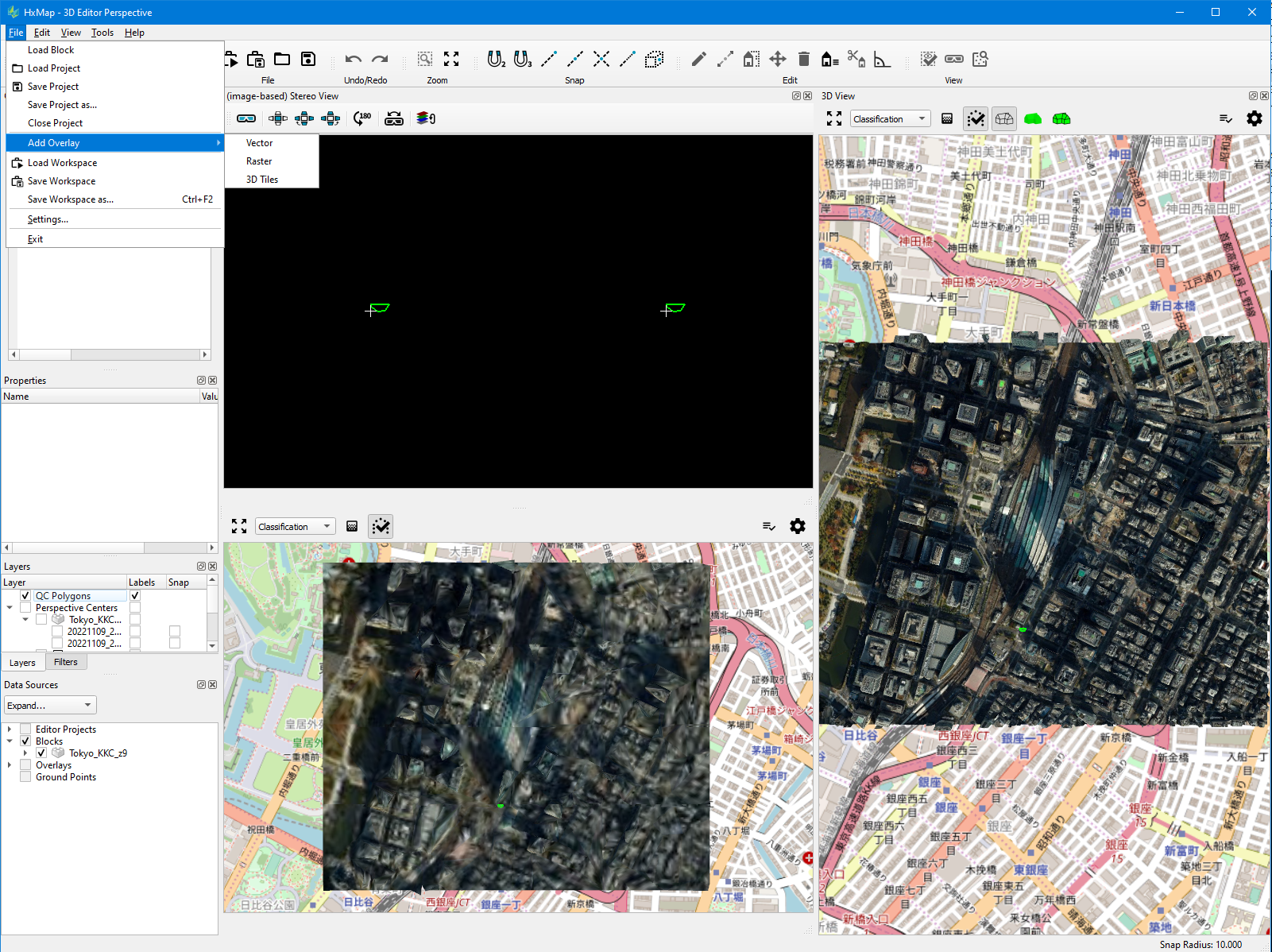
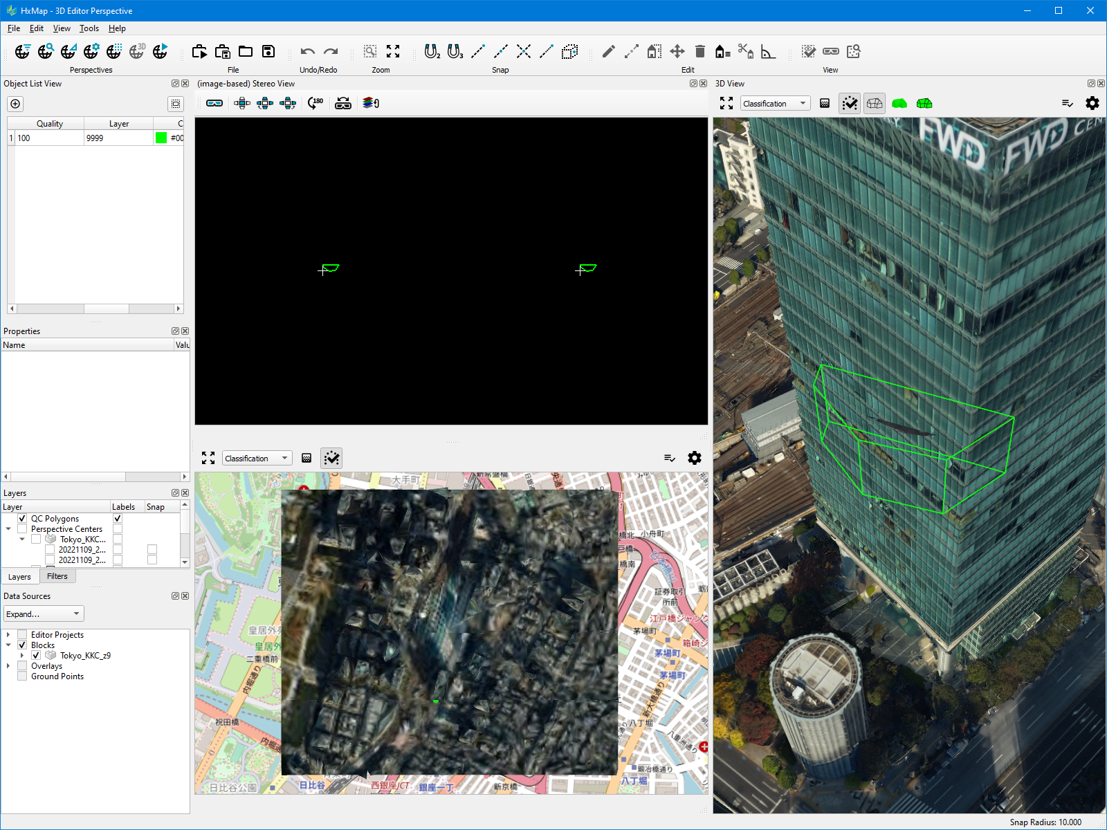
Quality Control
The 3D Editor perspective is used to QC and edit the generated mesh. During the QC process, the user collects volumes which should be added to or substracted from the mesh geometry. Once the volumes have been collected, an update job can be run to update the mesh geometry and textures, and recreate the true orthos.
|
QC Step |
Example |
Notes |
|---|---|---|
|
|
|
|
|
|
|
|
|
|
|
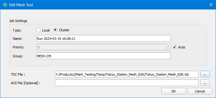
The Edit Mesh job result will be added to the parent job definition which is edited. |
Notes for 3D Advanced in HxMap 4.6
-
Coordinate Reference Systems which are supported for 3D Advanced Product Generation
-
EPSG systems
-
Ellipsoidal systems
-