HxMap provides tools to assess the quality of a misalignment refinement. This section presents the settings for the Quality-Assurance Tool (QA-Tool) and the acceptance criteria for approving a new camera or LiDAR misalignment.
The description on how to compute a Camera or LiDAR Misalignment can be found in HxMap documentation, it is not part of that documentation https://docs.hexagon.com/hxmap .
Image System
Settings
The misalignment computation for image systems requires to iteratively perform aerial triangulations to determine and verify the result, are available in statistics tab of the AT perspective in HxMap and in the AT report (hxmap_report.txt).
|
APM |
AT |
|---|---|
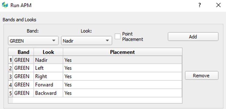
Note: APM settings are the same for misalignment computation and verification |
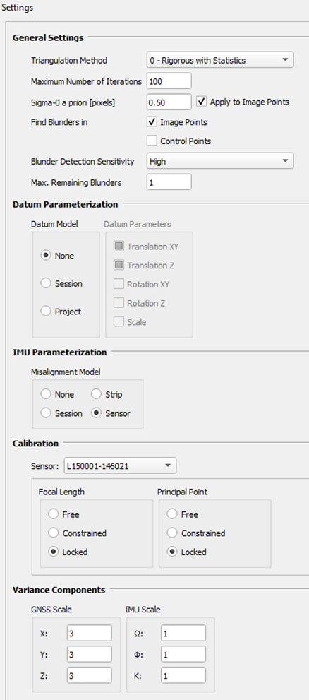
Triangulation Method = 0 Sigma-0 and image measurement precision => typically in a range of 0.30 – 0.50 px => adjust the a priori SD of image observations accordingly (use Apply to Image Points) Datum Parameterization => set as None (unless GCPs are used) IMU Parameterization => select Sensor Calibration => keep as Locked Variance Components => Use 3,3,3 for GNSS and 1,1,1 for IMU Scale |
Acceptance Criteria for Misalignment Verification
-
Misalignment angles less are than 3 x Standard Deviation
|
Example HxMap AT Report |
Example Statistics tab - HxMap AT Perspective |
|---|---|
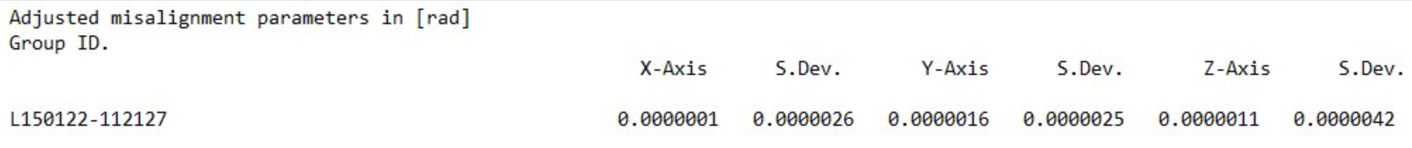
Units in radians |
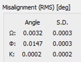
Units in degrees |
-
Review of imagery after Ingest using the computed misalignment values for RGBN and Swath alignment
In case the requirements are not met, a next iteration cycle should be performed with a newly created set of calibration files → Ingest → APM → AT
LiDAR System
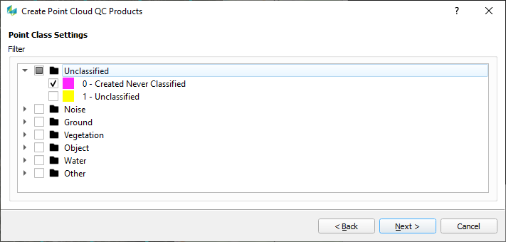
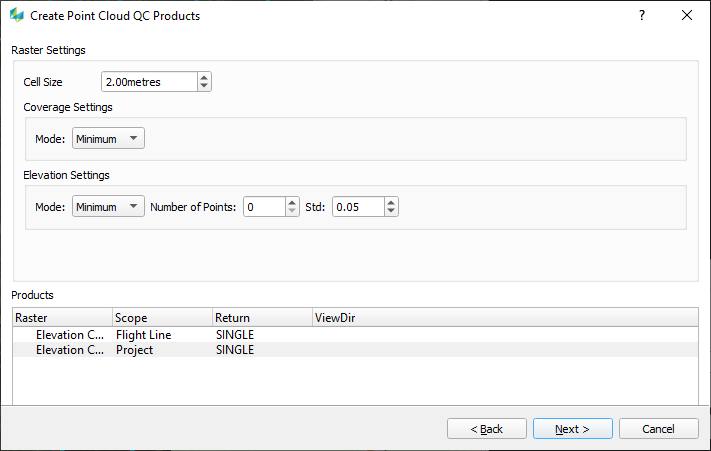
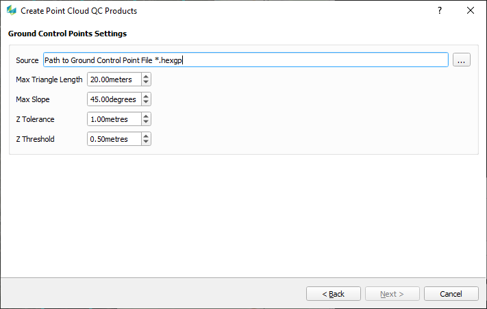
Settings for the LiDAR QA-Tool
The QA-Tool in HxMap generates raster files that can be used to interpret the misalignment results. The following QA settings should be applied:
|
Selected Class |
|---|
|
|
Raster Settings |
|
|
GCP Settings |
|
Acceptance for LiDAR Misalignment
Two aspects need to be checked with the computed data:
-
Quality of Exterior Orientation: This can be assessed using the Line-to-Line Comparison raster and against the Ground Control Points (GCPs).
-
Quality of Misalignment: This can only be evaluated using the Positive-Negative Comparison raster.
If the criteria for exterior orientation are not met, checking the misalignment is not meaningful.
Acceptance Criteria for Exterior Orientation (Positioning):
-
More than 90% of all cells in areas where adjacent lines overlap should show a difference of:
-
Less than 10 cm at 1700 m (60° FOV systems, approximately 170 m AGL/1 cm) before matching.
-
Or less than 7 cm at 2000 m (40° FOV systems, approximately 285 m AGL/1 cm) before matching.
-
-
The vertical median offset for session, block, and take to GCPs should be:
-
Less than 10 cm before matching.
-
Acceptance Criteria for Misalignment Verification:
-
More than 90% of all cells in the Positive-Negative Comparison raster should show a difference of:
-
Less than 10 cm at 1700 m (60° FOV systems, approximately 170 m AGL/1 cm) before matching.
-
Or less than 7 cm at 2000 m (40° FOV systems, approximately 285 m AGL/1 cm) before matching.
-