Misalignment Flight Pattern for Nadir Sensors
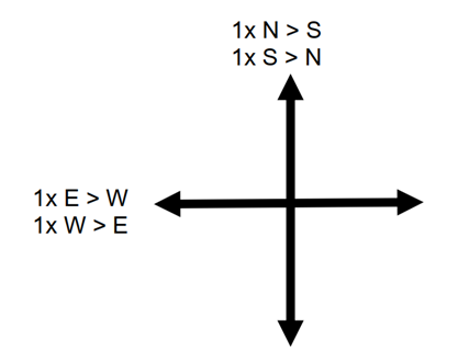
All sensors equipped with a nadir-looking camera—whether a single camera head or a composite-frame multi-camera subsystem—and whether or not they include LiDAR, utilize a “nadir-only” flight plan. This plan follows a simple four-line pattern.
This pattern can be used to perform a misalignment calibration on the entire sensor or specifically on the LiDAR or image module.
Below is a brief description of the flight line pattern used for nadir-only imaging systems, as well as for the LiDAR component of hybrid imaging/LiDAR systems:
-
Two pairs of opposing flight lines at right angles.
-
The typical orientation features two north-south lines and two east-west lines.
-
The line length is set long enough to create a fully overlapping region in the center of the cross pattern (refer to the darker purple area in the illustration below).

An optimal Misalignment Flight Area will have the following attributes:
-
contain large buildings such a warehouses or sports areas, buildings with sloped roofs are ideal
-
contain mainly hard solid surfaces like asphalt, concrete, bare soils, and/or short grass
-
should not contain large areas covering dense canopy, high vegetation or water bodies
-
have well known GCPs which can be used to checking absolute accuracy
Hyperion2+ based Systems (TerrainMapper-2 or CityMapper-2 LiDAR only)
|
Line Settings for Hyperion2+ based systems - Nadir Misalignment Plan (H2+) |
|||||
|---|---|---|---|---|---|
|
Line name |
Line Direction [deg] |
Scan Pattern |
Used Scan Rate [Hz] |
Target SNR |
Min Fwdlap [%] |
|
NS03_2000C |
0 |
Circle |
70-100 (Auto-Adjust) |
12 |
80 |
|
SN03_2000F |
180 |
Flower* |
150 |
7.1 |
80 |
|
EW04_2000C |
270 |
Circle |
70-100 (Auto-Adjust) |
12 |
80 |
|
WE04_2000F |
90 |
Flower* |
150 |
7.1 |
80 |
|
General line settings for Hyperion2+ based systems - Nadir Misalignment Plan (H2+) |
||||||||
|---|---|---|---|---|---|---|---|---|
|
Pulse Rate [Hz] |
FOV [deg] |
Max Alt AGL [m] |
Speed [kts] |
Noise Suppression |
Ch. Threshold |
Image Fwdlap [%] |
Line Length [km] |
Multi Pulse Mode |
|
~480,000 (Auto Adjust) |
40 |
2000 |
110 |
Medium |
150 |
80 |
5 |
5-7 |
|
Verification Lines for Hyperion2+ based systems - Nadir Misalignment Plan (H2+) |
|||||||
|---|---|---|---|---|---|---|---|
|
Line name |
Line Direction [deg] |
Scan Pattern |
AGL [m] |
Used Scan Rate [Hz] |
PRF [Hz] |
Target SNR |
Min Fwdlap [%] |
|
V01_2000C ** |
270 |
Circle |
1,500 - 2,500 |
150 (Auto Adjust - Gateless) |
1,000,000 - 2,000,000 |
12 |
80 |
|
V02_2000C ** |
90 |
Circle |
1,500 - 2,500 |
150 (Auto Adjust - Gateless) |
1,000,000 - 2,000,000 |
12 |
80 |
Hyperion3+ based Systems (CountryMapper, TerrainMapper-3)
|
specific line settings for Hyperion3+ based systems - Nadir Misalignment Plan (H3+) |
|||||
|---|---|---|---|---|---|
|
Line name |
Line Direction [deg] |
Scan Pattern |
Used Scan Rate [Hz] |
Target SNR |
Min Fwdlap [%] |
|
EW01_1700E |
270 |
Ellipse*** |
46.5 |
7.3 |
80 |
|
WE02_1700C |
90 |
Circle |
87 |
7.3 |
80 |
|
NS03_1700E |
180 |
Ellipse*** |
127 |
7.3 |
80 |
|
SN04_1700C |
0 |
Circle |
166.7 |
7.3 |
80 |
|
General line settings for Hyperion3+ based systems - Nadir Misalignment Plan (H3+) |
|||||||
|---|---|---|---|---|---|---|---|
|
Pulse Rate [Hz] |
FOV [deg] |
Max Alt AGL [m] |
Ground Speed [kts] |
Noise Suppression |
Channel Threshold |
Image Fwdlap [%] |
Line Length [km] |
|
1,200,000 |
60 |
1700 |
110 |
Medium |
125 |
80 |
5 |
IMPORTANT
Hyperion2+ misalignment flight lines must be recorded with Gated Mode. Disable Gateless MPiA recording mode option in Leica Aeroplan for all Hyperion2+Misalignment flight lines. Gateless MPiA mode can be used for Hyperion2+ verification lines.
|
Verification Lines for Hyperion3+ based systems - Nadir Misalignment Plan (H3+) |
|||||||
|---|---|---|---|---|---|---|---|
|
Line name |
Line Direction [deg] |
Scan Pattern |
AGL [m] |
Used Scan Rate [Hz] |
PRF [Hz] |
Target SNR |
Min Fwdlap [%] |
|
V01_2000C ** |
270 |
Circle |
1,500 - 2,500 |
166.7 (Auto Adjust) |
1,000,000 - 2,000,000 |
7.3 |
80 |
|
V02_2000C ** |
90 |
Circle |
1,500 - 2,500 |
166.7 (Auto Adjust) |
1,000,000 - 2,000,000 |
7.3 |
80 |
DMC-4
|
general line settings for DMC-4 - Nadir Flight Plan **** |
||
|---|---|---|
|
Max Alt AGL [m] |
Ground Speed [kts] |
Image Fwdlap [%] |
|
1700 |
110 |
80 |
* in case of a installation with optical window, replace the Flower pattern with Circular
** LiDAR verification lines - use of project settings is recommended or with higher PRF and Scan Rate as the Misalignment lines
*** in case of a installation with optical window, replace the Ellipse pattern with Circular
**** for DMC-4 the same lines as for TerrainMapper-3 can be used