Misalignment Flight Pattern for Oblique Sensors
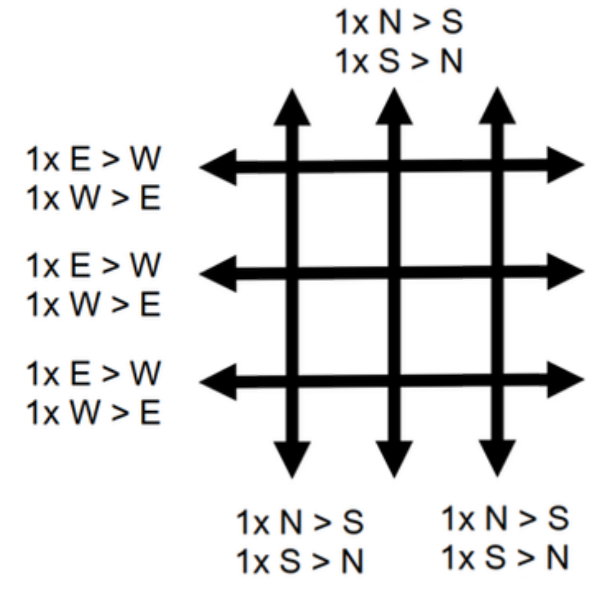
All sensors with oblique-looking cameras, whether or not they include LiDAR, use an “oblique” flight plan. This plan follows a 12-line “tic-tac-toe” pattern. Note that IMU misalignment calibration for hybrid imaging/LiDAR systems, after removal from or replacement in the aircraft, only requires the use of the “nadir sensor” flight pattern. The full pattern described below is only necessary when determining the misalignment for all imaging sensors in the oblique system, which is not typically required.
-
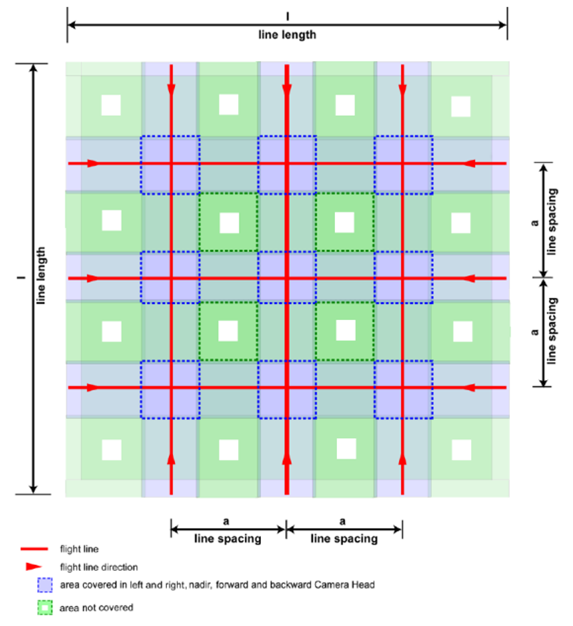
A “tic-tac-toe” pattern is necessary to compute a misalignment for oblique-looking cameras.
-
Six pairs of opposing flight lines at right angles are used, totaling 12 lines. This includes 2 LiDAR verification lines, which are part of the MFC Misalignment plan.
-
The typical line configuration uses 3 opposing pairs flown in a north-south orientation and 3 opposing pairs flown in an east-west orientation.
-
Line spacing (a in image below) is designed so that the left and right oblique image sensors have full overlap with the nadir sensor, with the nadir sensor positioned on the center flight lines of the “tic-tac-toe” pattern.
-
Line length (i in the image below; i is about 10km) ensures that the forward and backward looking sensors have full overlap with the nadir sensor, covering all three crossing flight lines.
-
If a LiDAR module is installed, the LiDAR sensor settings from the related nadir-only plans are used for the center lines of the misalignment flight pattern (refer to the darker purple areas in the illustration below).
-
If a LiDAR only misalignment is needed, use the settings form TerrainMapper-2 in the Nadir only Misalignment section.
An optimal Misalignment Flight Area will have the following attributes:
-
contain large buildings such a warehouses or sports areas, buildings with sloped roofs are ideal
-
contain mainly hard solid surfaces like asphalt, concrete, bare soils, and/or short grass
-
should not contain large areas covering dense canopy, high vegetation or water bodies
-
have well known GCPs which can be used to checking absolute accuracy
|
Line Settings for Hyperion2+ based systems - Oblique Flight Plan |
|||||
|---|---|---|---|---|---|
|
Line name |
Line Direction [deg] |
Scan Pattern |
Used Scan Rate [Hz] |
Target SNR |
Min Fwdlap [%] |
|
NS01_1700C |
0 |
Circle |
70-100 (Auto-Adjust) |
12 |
80 |
|
SN01_1700F |
180 |
Flower* |
150 |
7.1 |
80 |
|
NS02_1700C |
0 |
Circle |
70-100 (Auto-Adjust) |
12 |
80 |
|
SN02_1700F |
180 |
Flower * |
150 |
7.1 |
80 |
|
NS03_1700C ** |
0 |
Circle |
70-100 (Auto-Adjust) |
12 |
80 |
|
SN03_1700F ** |
180 |
Flower * |
150 |
7.1 |
80 |
|
EW04_1700C ** |
270 |
Circle |
70-100 (Auto-Adjust) |
12 |
80 |
|
WE04_1700F ** |
90 |
Flower * |
150 |
7.1 |
80 |
|
EW05_1700C |
270 |
Circle |
70-100 (Auto-Adjust) |
12 |
80 |
|
WE05_1700F |
90 |
Flower * |
150 |
7.1 |
80 |
|
EW06_1700V *** |
270 |
Circle |
150 |
12 |
80 |
|
WE06_1700V *** |
90 |
Circle |
150 |
12 |
80 |
|
general line settings for Hyperion2+ based systems - Oblique Flight Plan |
||||||||
|---|---|---|---|---|---|---|---|---|
|
Pulse Rate [Hz] |
FOV [deg] |
Max Alt AGL [m] |
Speed [kts] |
Noise Suppression |
Ch. Threshold |
Image Fwdlap [%] |
Line Length [km] |
Multi Pulse Mode |
|
500000 |
40 |
1700 |
110 |
Medium |
150 |
80 |
5 |
5-7 |
IMPORTANT
Hyperion2+ misalignment flight lines must be recorded with Gated Mode. Disable Gateless MPiA recording mode option in Leica Aeroplan for all Hyperion2+Misalignment flight lines. Gateless MPiA mode can be used for Hyperion2+ verification lines.
|
Verification Lines for Hyperion2+ based systems - Nadir Misalignment Plan (H2+) |
|||||||
|---|---|---|---|---|---|---|---|
|
Line name |
Line Direction [deg] |
Scan Pattern |
AGL [m] |
Used Scan Rate [Hz] |
PRF [Hz] |
Target SNR |
Min Fwdlap [%] |
|
EW06_1700V*** |
270 |
Circle |
1,700 |
150 (Auto Adjust - Gateless) |
1,000,000 - 2,000,000 |
12 |
80 |
|
WE06_1700V*** |
90 |
Circle |
1,700 |
150 (Auto Adjust - Gateless) |
1,000,000 - 2,000,000 |
12 |
80 |
* in case of a installation with optical window, replace the Flower pattern with Circular
** LiDAR Misalignment or nadir camera only Misalignment – see TerrainMapper-2 as reference
*** LiDAR verification lines - with different PRF settings of 2 MHz