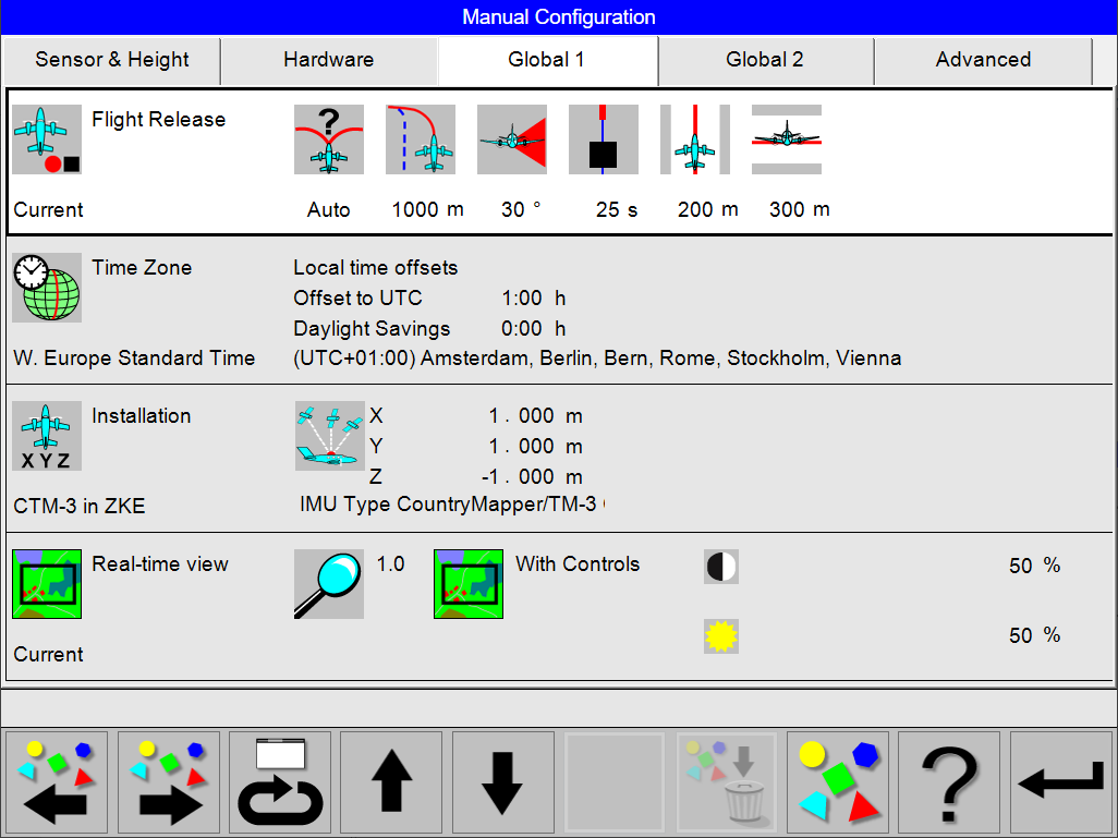
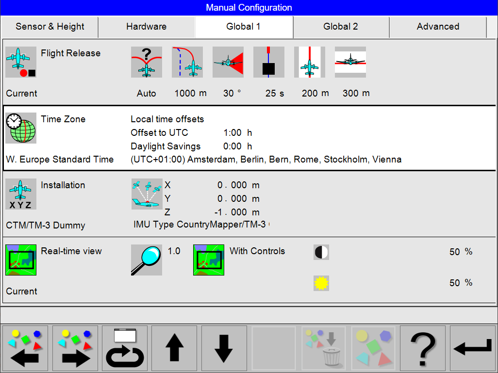
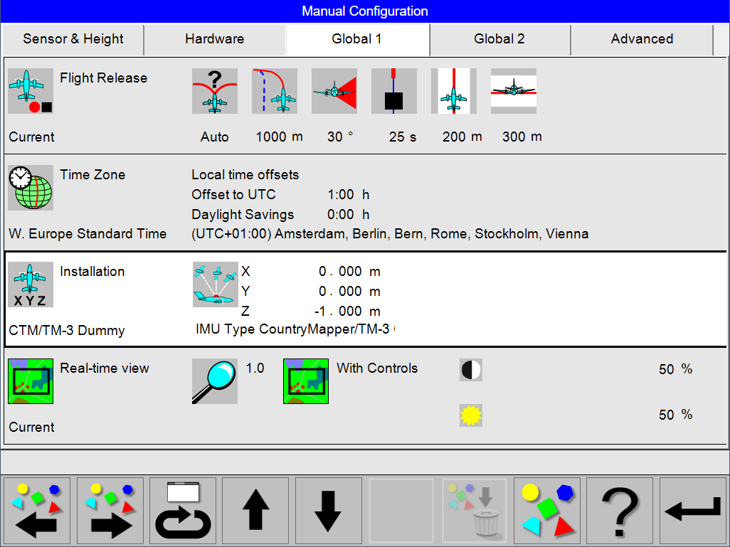
The Global 1 tab show a summarized overview of the parameters of the following configuration sections are given.
-
Flight release
-
Time Zone
-
Installation
-
Real-time view
Enter Global 1 Configuration
Select
Select
In the main configuration dialog a summarized overview of the parameters of the selected configuration is given. This is also the entry point for changing, editing and creating configurations.
Navigation and Interaction
The selected configuration is shown with a whit background and marked with a thicker outline.
Use
Use
Select
Select
Select
If the predefined sets matches, select [Return] to open the dialog for ‘Save’, ‘Save as’ or ‘Cancel’.
Configuration of Flight Guidance & Sensor Release Configuration options
Introduction
During a flight plan controlled flight Leica FlightPro calculates the optimal approach from the position of the aircraft to the start of the line. The user can set various parameters to influence the calculation. The settings are made in the dialogs described in the following sections of this paragraph.
Names of pre-configured ‘Flight Release’ configuration sets
These names have been given so as to be self-explanatory according to the conventions listed below:
|
Name |
Description |
|---|---|
|
Slow AC |
Parameters suitable for aircraft flying at 70 knots to 120 knots |
|
Standard AC |
Parameters suitable for aircraft flying at 110 knots to 170 knots |
|
Fast AC |
Parameters suitable for aircraft flying at 150 knots to 250 knots |
|
Very fast AC |
Parameters suitable for aircraft flying at 200 knots to 400 knots |
Guidance Project
The various guidance options are configured in the Guidance Project.
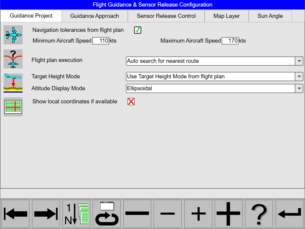
Guidance Project tab parameters
|
Parameter |
Sensor Type |
Options |
Remarks |
|---|---|---|---|
|
Navigation tolerances from flight plan |
All |
Navigation tolerances from loaded flight plan are used when Navigation tolerances from flight plan is selected |
|
|
Minimum Aircraft Speed |
All |
FlightPro never shows a ground speed slower than the configured Minimum Aircraft Speed value |
|
|
Maximum Aircraft Speed |
All |
FlightPro never shows a ground speed faster than the configured Maximum Aircraft Speed value |
|
|
Flight plan execution |
All |
Auto search for nearest route |
During flight execution, Leica FlightPro suggests the next approach to the closest line within the project. Leica FlightPro selects the line direction. Any time the user can select a different line or direction of approach. |
|
Nearest line, flown in planned direction |
During flight execution, Leica FlightPro suggests the next approach to the closest line within the project. The line direction is as planned. Any time the user can select a different line or direction of approach. |
||
|
Nearest line, flown reverse to planning |
During flight execution, Leica FlightPro suggests the next approach to the closest line within the project. The line direction is reverse to the planning. Any time the user can select a different line or direction of approach. |
||
|
Reverse sequence, shortest line approach |
During flight execution, Leica FlightPro suggests the next approach to the line next in reverse sequence. Leica FlightPro selects the line direction. The sequence is defined in Leica MissionPro during flight planning. Any time the user can select a different line or direction of approach. |
||
|
Target height mode |
All |
Constant altitude above ellipsoid |
The desired altitude in the Flying altitude control shows an ALT MSL value to maintain a flight at constant flying height above mean see level. The reference value is derived from the flight plan. This mode is typically used for fixed-wing aircraft. |
|
Constant altitude above ground level - Follow Terrain Topography |
The desired altitude in the Flying altitude control shows an ALT MSL value to maintain a flight at constant flying height above ground level. The reference values are either taken from the flight plan if a DTM was used. This mode is typically used with LIDAR for corridor mapping with Helicopters. |
||
|
Use Target Height Mode from flight plan |
The Target Height Mode is taken from the loaded flight plan |
||
|
Altitude Display Mode |
All |
|
Altitude is displayed in the selected Altitude Display Mode |
|
Show local coordinates if available |
All |
|
If checked local coordinates are displayed in the position control. Local coordinates are available if the flight plan was made in local coordinates or if a map with local coordinates is loaded by Leica FlightPro. |
Important: Constant altitude above ground level - Follow Terrain Topography mode works only if a DTM was used during flight planning in Leica MissionPro. This mode is typically only used for LIDAR missions.
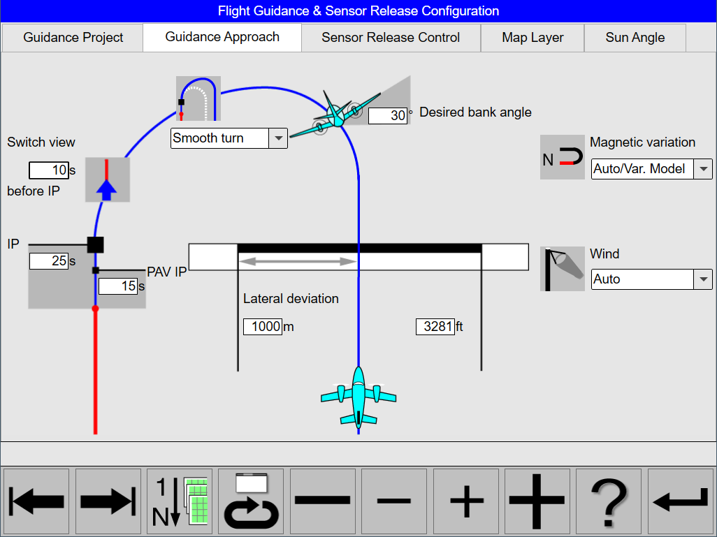
Guidance Approach
The various guidance for approach options are configured in the Guidance Approach .
Guidance Approach tab parameters
|
Parameter |
Setting |
Remarks |
|---|---|---|
|
Lateral deviation |
Typical range1000 m to 2500 m. |
If the lateral deviation from the ideal course exceeds the specified value, a new ideal course is calculated from the current position of the aircraft. The faster the aircraft the larger the distance should be. If a pilot is not experienced to fly with Leica FlightPro flight guidance, this value should be set to a larger number than usual. |
|
Desired bank angle |
Typical value 15° to 25° For deeply-coupled systems turns up to 45° are possible |
Leica FlightPro calculates the turns according to the desired bank angle. If the system provides a deeply-coupled real-time solution, a corresponding icon is displayed on the GNSS control. |
|
Short turn / Smooth turn |
Short turn is typically selected if wind is taken into account |
In this case the last turn is calculated as all other turns during approach. The desired bank angle is taken for calculation. |
|
Smooth turn is typically selected if wind is not taken into account |
In this case the last turn is calculated differently than the other turns during approach. The turn starts at the desired bank angle and becomes smoother the closer the IP is. The graphic in the view illustrates the smooth turn. A smooth turn allows corrections during final approach without the danger of exceeding the maximum bank angle. |
|
|
Switch view before IP |
Typically 15 seconds |
Flying time left to the IP along suggested flight when Leica FlightPro switches to the In-line navigation view. The In-line navigation view allows a more precise final approach |
|
IP (Initial Point) |
Typically 20 to 60 seconds |
A certain time (in seconds) ahead of the first release point on the flight line, Leica FlightPro computes a fictitious IP along the direction of approach. |
|
PAV IP |
Typically 10 to20 seconds. |
A certain time (in seconds) ahead of the first release point on the flight line, Leica FlightPro switches the PAV to operational mode ON-AUTO. |
|
Wind |
No (cross) |
No wind is taken into account to calculate the suggested flight path. |
|
Set |
User setting for wind direction and wind speed are taken into account to calculate the suggested flight path. |
|
|
Auto |
Leica FlightPro detects wind direction and wind speed automatically. The results are taken into account to calculate the suggested flight path. |
|
|
Magnetic variation |
OFF/True North |
Directions are displayed true north. |
|
Auto/ Var Model |
Leica FlightPro applies the magnetic variation for a line by using the US/UK World Magnetic Model. Details to the magnetic model see: http://www.ngdc.noaa.gov/seg/WMM/. |
|
|
User Def |
User input of magnetic variation |
Configuration of Guidance Approach
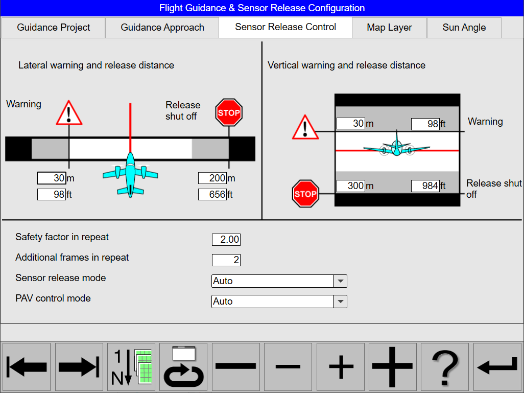
Sensor Release Control
The various sensor release options are configured in the Sensor Release Control.
Sensor Release Control tab parameters
|
Parameter |
Setting |
Remarks |
|---|---|---|
|
Lateral warning |
Typical value75 m - 150 m |
If this lateral distance is exceeded when flying along the line, the aircraft points to the grey warning bar in the line deviation control which is displayed on the In-line navigation view. See illustration in Figure 145 on Page 537. |
|
Lateral release shut-off |
Typical value 200 m - 400m |
If the specified permissible lateral deviation is exceeded when flying along a line, the aircraft points to the solid bar in the line deviation control which is displayed on the Inline navigation view. The sensor release is blocked. No image data will be recorded as long as the deviation is exceeded. See illustration in Figure 145 on Page 537. |
|
Vertical warning |
Typical value100 m |
If this vertical distance is exceeded, the actual altitude is displayed in the area of one of the grey warning bars which are displayed on the Flying altitude control. |
|
Vertical release shut off |
Typical value 300 m |
If this vertical distance is exceeded, the actual altitude is displayed in the area of one of the black bars which are displayed on the Flying altitude control. The sensor release is blocked. No image data will be recorded as long as the deviation is exceeded. |
|
Additional frames in repeat |
Typical value1 to 3 |
If only a missed part in a flight line is repeated, Leica FlightPro extends for the re-flight the repeated segment of the line by a number of frames. This is to avoid data gaps. The safety factor is used to adjust the overlap of the line segment. The higher the number of frames the longer the overlapping section of the line segments. |
|
Sensor release mode |
Auto |
In mode ‘Auto’ the Sensor is released according to the events defined in the flight planning. |
|
Inactive |
In mode ‘Inactive’ all planned release events are suppressed. The Sensor configuration is set according to the flight planning or to user actions. If the user toggles the mode back to ‘Auto’ on an observation period, image data recording starts until the end of the observation period or until the sensor mode is reset to ‘inactive’. |
|
|
Leica PAV200/PAV100 mode |
AUTO |
In this mode Leica FlightPro controls the stabilization mode of the Leica PAV80/PAV100 by software commands during project execution. Leica FlightPro commands the Leica PAV80/PAV100 to switch OFF stabilization during approach and turns. Leica FlightPro commands the Leica PAV80/PAV100 to switch ON stabilization when flying along a flight line from the point defined by the parameter ‘PAV initialization time’ till the end of the flight line. See illustration in Figure 146 on Page 538. |
|
ON-AUTO |
This setting is to override Leica FlightPro. The Leica PAV80/PAV100 operational mode is set to ON during the entire flight .A warning message will be displayed in the status line. |
|
|
OFF MANUAL |
This setting is to override Leica FlightPro. The Leica PAV80/PAV100 operational mode is set to OFF during the entire flight .A warning message will be displayed in the status line. |
Typical configuration settings for various aircraft types
|
Parameter Group |
Parameter |
Slow aircraft |
Standard aircraft |
Fast aircraft |
Very fast aircraft |
|---|---|---|---|---|---|
|
Guidance Project |
Flight plan execution |
Auto search for nearest route |
Auto search for nearest route |
Auto search for nearest route |
Auto search for nearest route |
|
Guidance Approach |
Lateral warning |
1000 m |
1250 m |
1500 m |
2500 m |
|
Desired bank |
27 ° |
27 ° |
27 ° |
27 ° |
|
|
Turn |
smooth |
smooth |
smooth |
short |
|
|
Switch view before IP |
20 sec |
20 sec |
20 sec |
20 sec |
|
|
IP |
25 sec |
30 sec |
40 sec |
60 sec |
|
|
PAV IP |
15 sec |
15 sec |
20 sec |
20 sec |
|
|
Magnetic variation |
Auto |
Auto |
Auto |
Auto |
|
|
Wind |
Auto |
Auto |
Auto |
Auto |
|
|
Sensor release control |
Lateral warning |
75 m |
75 m |
100 m |
150 m |
|
Lateral release shut off |
200 m |
250 m |
300 m |
400 m |
|
|
Vertical warning |
100 m |
100 m |
100 m |
100 m |
|
|
Vertical release shut off |
300 m |
300 m |
300 m |
300 m |
|
|
Safety factor in repeat |
2 x |
2 x |
2 x |
2 x |
|
|
Sensor release mode |
AUTO |
AUTO |
AUTO |
AUTO |
|
|
PAV80/PAV100 operational mode |
AUTO |
AUTO |
AUTO |
AUTO |
Note: The parameter desired bank angle is used by Leica FlightPro to compute the radius in the turn sections of the suggested flight path. If the aircraft is flown with a bank angle equal to the ‘desired bank angle’, the Leica FlightPro turn radius matches with the aircraft’s turn radius. Whether the turn radius matches in a real flight depends on the aerodynamic characteristics of the aircraft. If the turn radius does not match, adjust in Leica FlightPro configuration the desired bank angle. To adjust increase or decrease the value until the turn radius flown with the aircraft at desired bank angle is coincident with the flight path suggested by Leica FlightPro
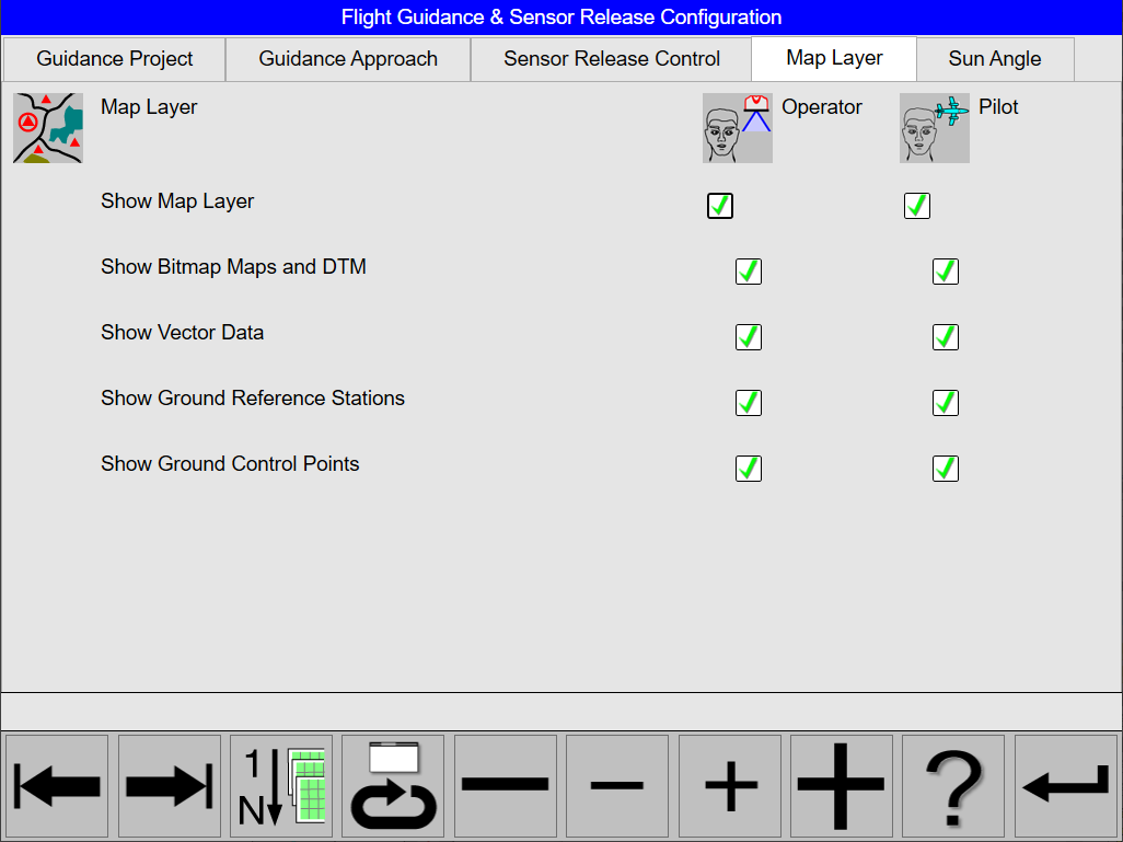
Map Layer
The various map options are configured in the Map Layer.
Map Layer tab parameters
|
Parameter |
Setting |
Remarks |
|---|---|---|
|
Show map layer |
Unselected |
No data are displayed on the map layer |
|
Selected |
Bitmap maps, the vector data, location of Ground Control Points and GNSS ground reference stations are displayed independently on the Operator and Pilot interface. Each data type can be individually checked. Bitmap maps have to be uploaded to the airborne system. DTM data have to be installed on the airborne system. All other map layer data are uploaded to the airborne system with the flight plan. These data are the ‘Graphic elements’ and/or ‘Ground control points’ added to the project during flight planning in Leica MissionPro. |
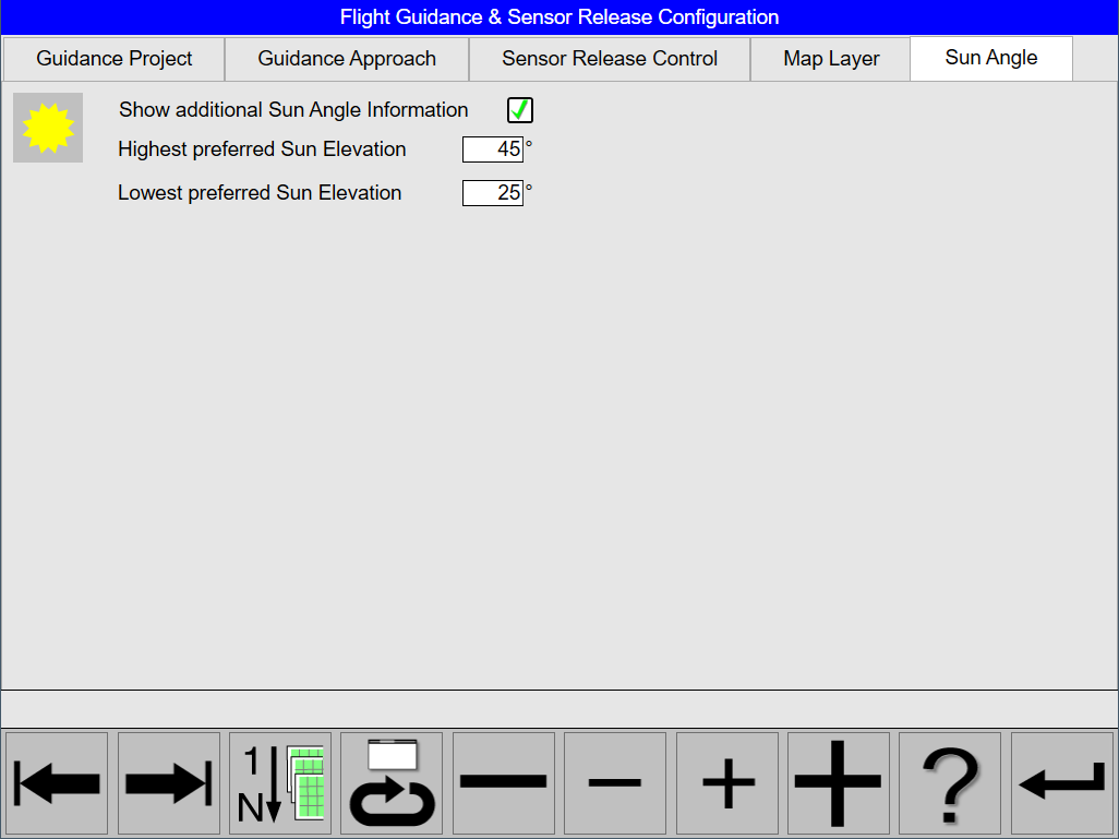
Sun Angle
The sun angle options and parameters are configured in the Sun Angle.
Sun Angle tab parameters
|
Parameter |
Setting |
Remarks |
|---|---|---|
|
Show additional Sun Angle Information |
|
If Show additional Sun Angle Information option is selected, the the additional sun angle information is shown in the Sun Angle control. |
|
Highest preferred Sun Elevation |
1° - 89° |
Highest preferred Sun Elevation value must be larger than the Lowest preferred Sun Elevation value. |
|
Lowest preferred Sun Elevation |
1° - 89° |
Highest preferred Sun Elevation value must be larger than the Lowest preferred Sun Elevation value. |
Time Zone
All time zones are predefined. Daylight saving is handled by the operating system.
Installation
Important: Store the installation parameter with a unique name to reduce mistakes. Use the aircraft registration number (also called tail number) as a name to save the installation parameters.
System Installation Parameters
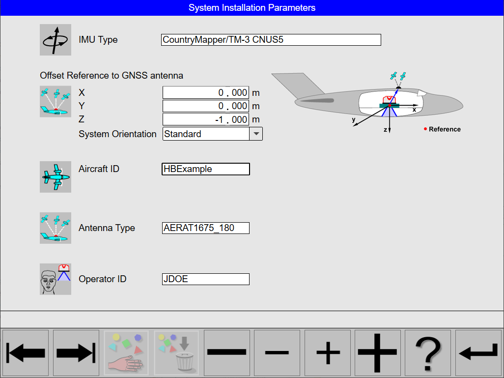
In this dialog the following parameters are defined:
-
IMU type
-
Offset Reference to GNSS antenna
-
System Orientation
-
Standard
-
Reverse
-
-
Aircraft identifier
-
Antenna Type
-
Operator ID
Real-time view
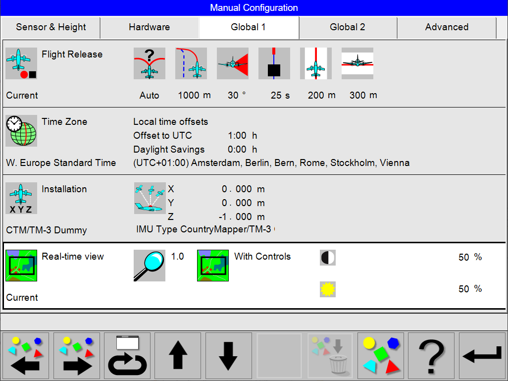
Real-time view Configuration
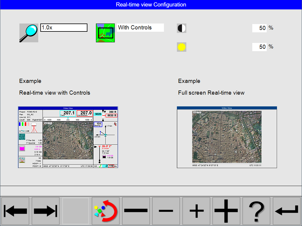
In this dialog the following can be set:
-
default real-time view
-
default displayed brightness
-
default displayed contrast