The operator configures and controls the airborne system through the OC61 Operator Console and PD61 Pilot Display. No mouse or keyboard is necessary. Leica FlightPro features a graphical user interface with the following main features:
-
Icons on large buttons
-
Touchscreen interface
-
Pre-defined system configurations
-
On-line help
GUI features
Controls to group information
The graphical user interface ensures a uniform look and feel. During flight execution, information is provided to the user in a simplified form. Closely related information is displayed in controls. A control is an area which displays standardized information. For example relevant information about the line in execution is displayed in the line progress control. The controls are part of the different selectable views. This ensures that the information always appears the same on all views.
Use of colour to group information
For simpler identification information related to each other is displayed in the same colour. For example:
-
Cyan is used as main colour for the aircraft. Therefore, the aircraft symbol is cyan,
the aircraft’s track over ground and the aircraft’s altitude are displayed in a field with cyan
background or frame. -
Red is used for the flight line. Therefore, the current flight line is displayed as a red line in
the graphics and the values for desired altitude and the target GS are displayed in a red
frame. -
Yellow background is used for fix settings
Figurative language on icons
-
self-explanatory, easy to learn
-
same key figures are used in many icons
-
hot key buttons for quick change of view during flight execution
-
each component of the system has a unique symbol
-
well known symbols from other GUI are used in icons
Key Figures
The following basic symbols are used in various buttons of Leica FlightPro.
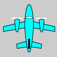
Aircraft
Indicates flight and flight-related data or activities. Used in combination with flight line, heights and flight plan
|

|

|

|
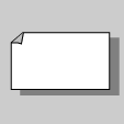
Data
Indicates data. Used for flight plan and projects.
|

|

|

|
Red Line
Indicates flight line.
Used in combination with flight line selection, project/filter and aircraft.

|

|

|

|

|
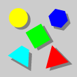
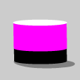
Various Shapes
Indicates system configuration. Used in combination with manual configuration, other data set, etc.
|

|

|

|

|
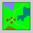
Stylized Terrain
Indicates image. Used in combination functions to adjust image display.
|

|

|

|

|
Magnifying glass
Indicates view of details. Used in combination with image for zoom in/out and to show more information.

|

|

|

|

|
Funnel
Indicates data filtering. Used in combination with devices and actions.

|

|
|

|

|
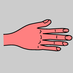
Hand
Indicates manual actions. Used in combination with other symbols.
|
|
|

|

|
Key symbols for system components
Sensor symbol
Indicates information related to Camera Head. Used in combination to show next information, data filter etc.
|

|
|

|
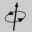
IMU symbol
Indicates Inertial Measurement Unit (IMU). Used also in combination with data filter.
|

|

|
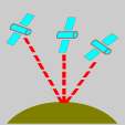
Satellites symbol
Indicates Global Positioning System (GNSS). Used also in combination with data filter.
|

|

|
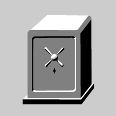
Mass Memory symbol
Indicates Mass Memory (MM30). Used also in combination with data filter and actions.
|

|

|

|
Internal Memory symbol
Indicates internal memory of the system. Used mainly in the data handling dialogues (upload, download, delete).
|

|

|
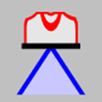
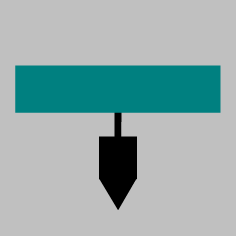
Mount symbol
Indicates Gyro-stabilized mount. Used to display status or to set operational status or mount manually.
|

|

|

|
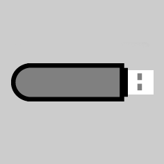
USB flash drive
Indicates external memory and transfer media like USB flash drive. Used in the data handling dialogues (upload, download, delete).
|

|
Button Types
Workflow
Examples:

|
Enter data handling module |
|
|
Enter configuration module |
|
|
Enter flight execution module |

|
Return to previous menu |
Activity
Examples:

|
Start image data recording |

|
Stop image data recording |

|
Select to fly previous line |

|
Decrease value |
Change of view
Examples:
|
|
Show Pod status view |
|
|
Show Project view |

|
Show Nose-up navigation view. |

|
Show next sub-view. |
Button change
Examples:

|
Change buttons on toolbar-display buttons related to current view |

|
Change buttons on toolbar-display buttons to select view |
|
|
Change buttons on toolbar display buttons to adjust display of images |

|
Change buttons on toolbar-display buttons to set filter to hide information. |